
Gigabyte Ultra Durable Z370 HD3 Motherboard Review
As is the case with every manufacturer, they try to cover all the segments of the PC motherboard market be it budget users, mid-range or high-end enthusiasts. Gigabyte is no exception to that. That is why we would be taking a look at their entry-level Intel Z370 chipset motherboard aimed for the users who would not want to spend a hefty amount on the motherboard and would still want to experience the functionality of the Intel Z370 chipset. The motherboard under light is their Ultra Durable Z370 HD3. This motherboard packs some nice features which include:
- Supports 8th Gen Intel® Core™ Processors
- Dual Channel Non-ECC Unbuffered DDR4, 4 DIMMs
- Intel® Optane™ Memory Ready
- 2-Way CrossFire™ Multi-Graphics [Not SLI ready]
- Intel® Gigabit LAN with cFosSpeed Internet Accelerator Software
- Ultra Durable™ 25KV ESD and 15KV Surge LAN Protection
- High-Quality Audio Capacitors and Audio Noise Guard with LED Trace Path Lighting
- Ultra-Fast M.2 with PCIe Gen3 x4 & SATA interface
- RGB FUSION supports RGB LED strips in 7 colors
- Smart Fan 5 features Multiple Temperature Sensors and Hybrid Fan Headers with FAN STOP
- Anti-Sulfur Resistors Design
- APP Center Including EasyTune™ and Cloud Station™ Utilities
- Product: Ultra Durable Z370 HD3
- Manufacturer: GIGABYTE
- Price: PKR 20,000/- [At the time of the review]
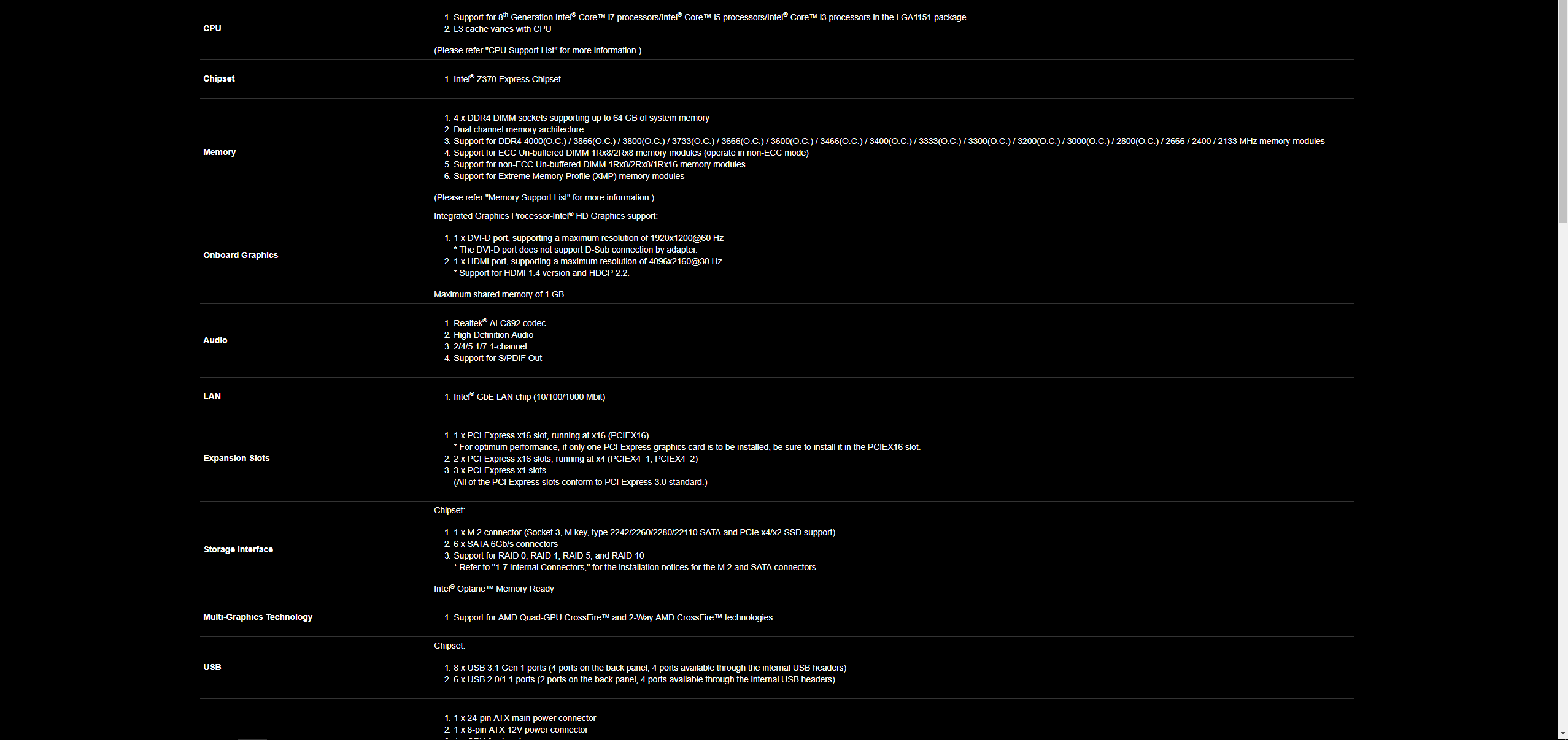
Specifications


Packaging and Unboxing
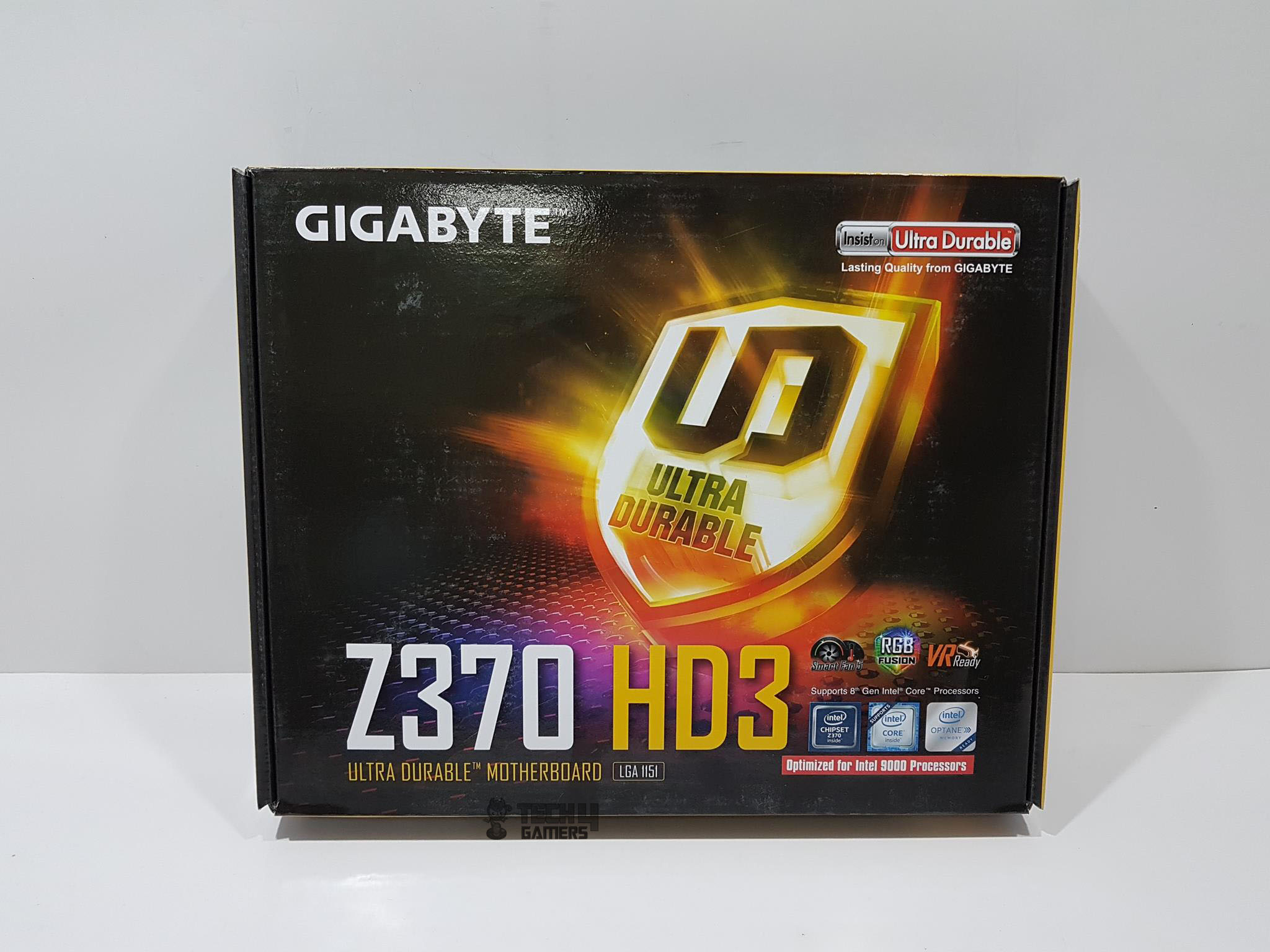
The motherboard is shipped inside a cardboard-based packing box. The front side of the packing box has Gigabyte brand name printed on the top left. Ultra Durable is printed on the top right side. The main picture on this side is of the Ultra Durable logo from Gigabyte. Their tag line is “Lasting Quality from Gigabyte” hence the term Ultra Durable. Z370 HD3 Ultra Durable Motherboard is printed at the bottom. The motherboard packs SmartFan 5, RGB Fusion, and is VR ready. It is optimized for Intel Core series of the processors in the 9th generation and has LGA 1151 socket.
The backside of the packing box has a picture of the motherboard on the left side. Ultra Durable Motherboard Z370 HD3 is printed on the top. Salient feature highlights like SmartFan 5, Fan Stop, cFos 3x ESD, high-quality onboard sound solution, RGB Fusion to name a few are printed on the main section. Salient specifications are printed in tabular format below the picture of the motherboard. Gigabyte brand name and logo are printed at the bottom right.
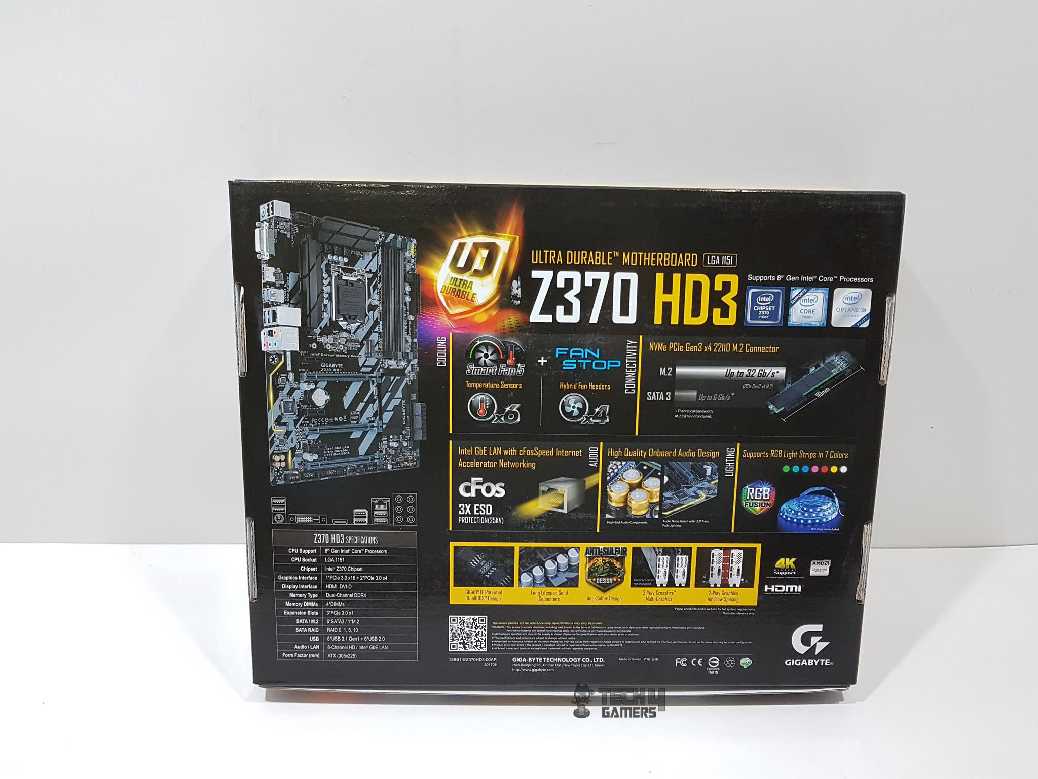
The rear side of the packing box has motherboard’s salient features in 18 languages.
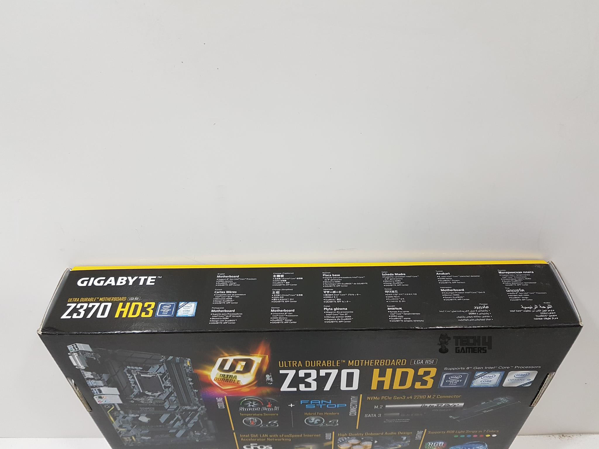
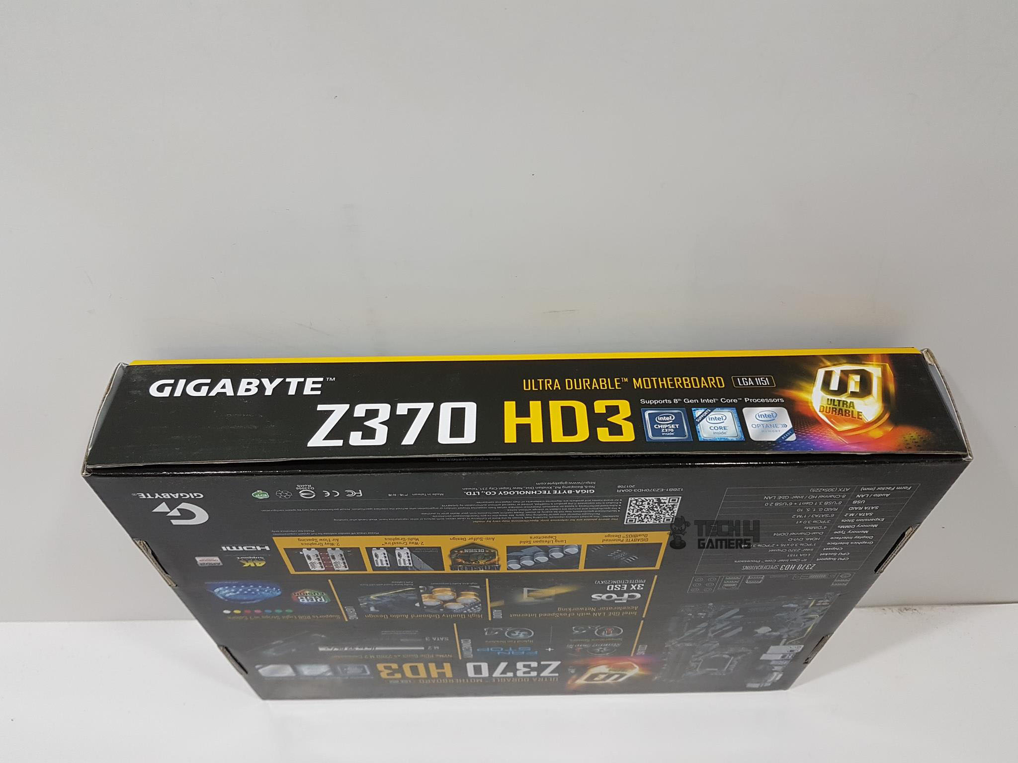
The opening and the left sides of the packing box has Gigabyte printed on the top left. Z370 HD3 is printed at the middle bottom. The Ultra Durable logo is printed on the rightmost side.
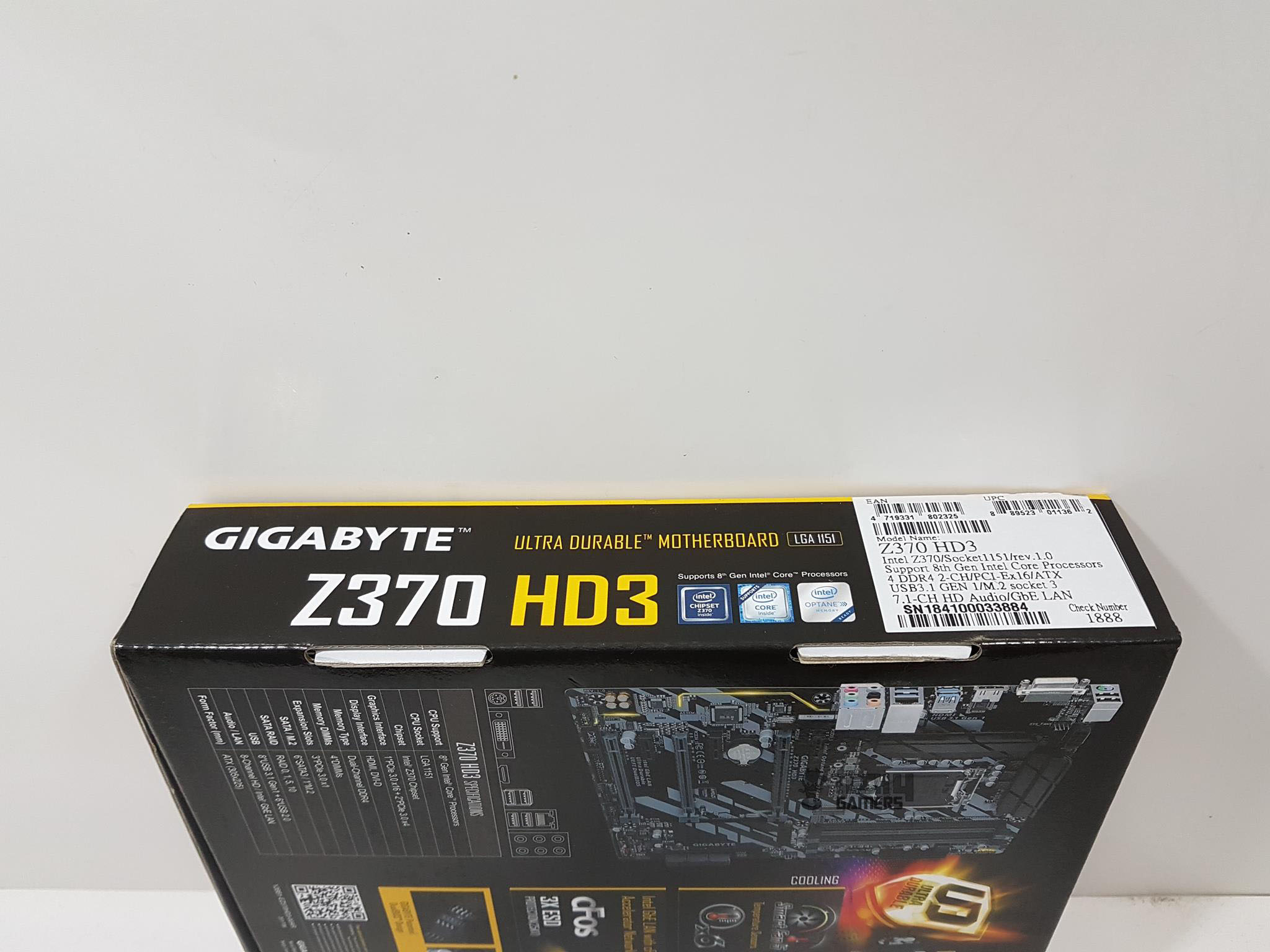
The right side of the packing box is identical to the layout on the left side but there is a sticker pasted on its rightmost side with the serial no, EAN, UPC info labels and check no.
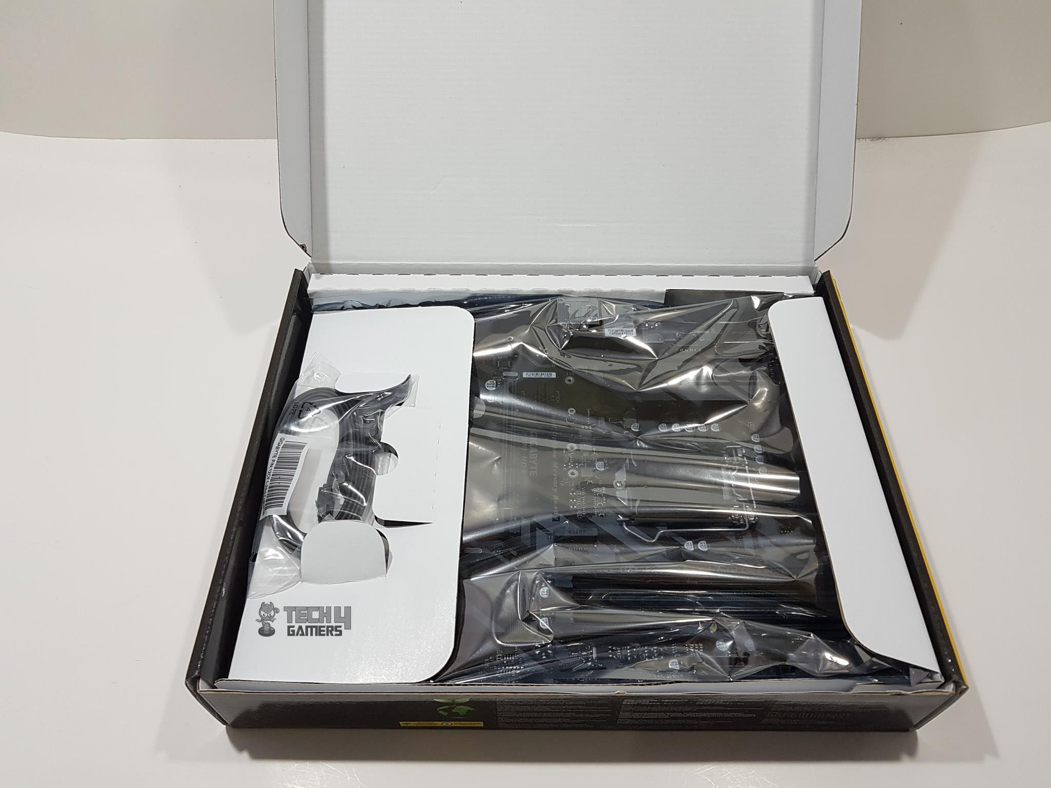
Opening the box will show a white color of the inner side of the packing box. SATA cables can be seen in their holder on the top of the motherboard which is packed inside an anti-static sheet.
Accessories and Contents
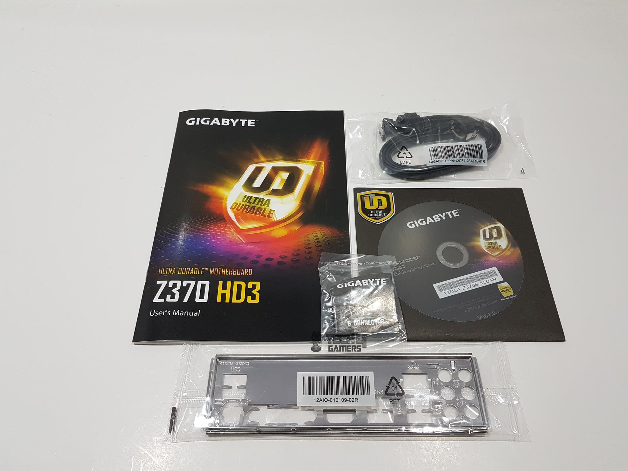
There are not a bunch of accessories supplied with this motherboard as this is not their high-end solution.
- I/O Shield
- G Connector
- Installation Disk
- User Manual
- 2x SATA Cables
Closer Look
The Gigabyte Ultra Durable Z370 HD3 is a budget-friendly offer for the users who would want to experience this chipset but don’t want to spend lavishly as Gigabyte has got them covered for good if not better. It is time to take a closer look at the motherboard and see what it offers to the gamer and user alike. Please, note that this is not a media sample but a retail unit arranged by the Gigabyte through their partner. Hence, we did not remove the heat sink covers to look up the VRM and MOSFETs.

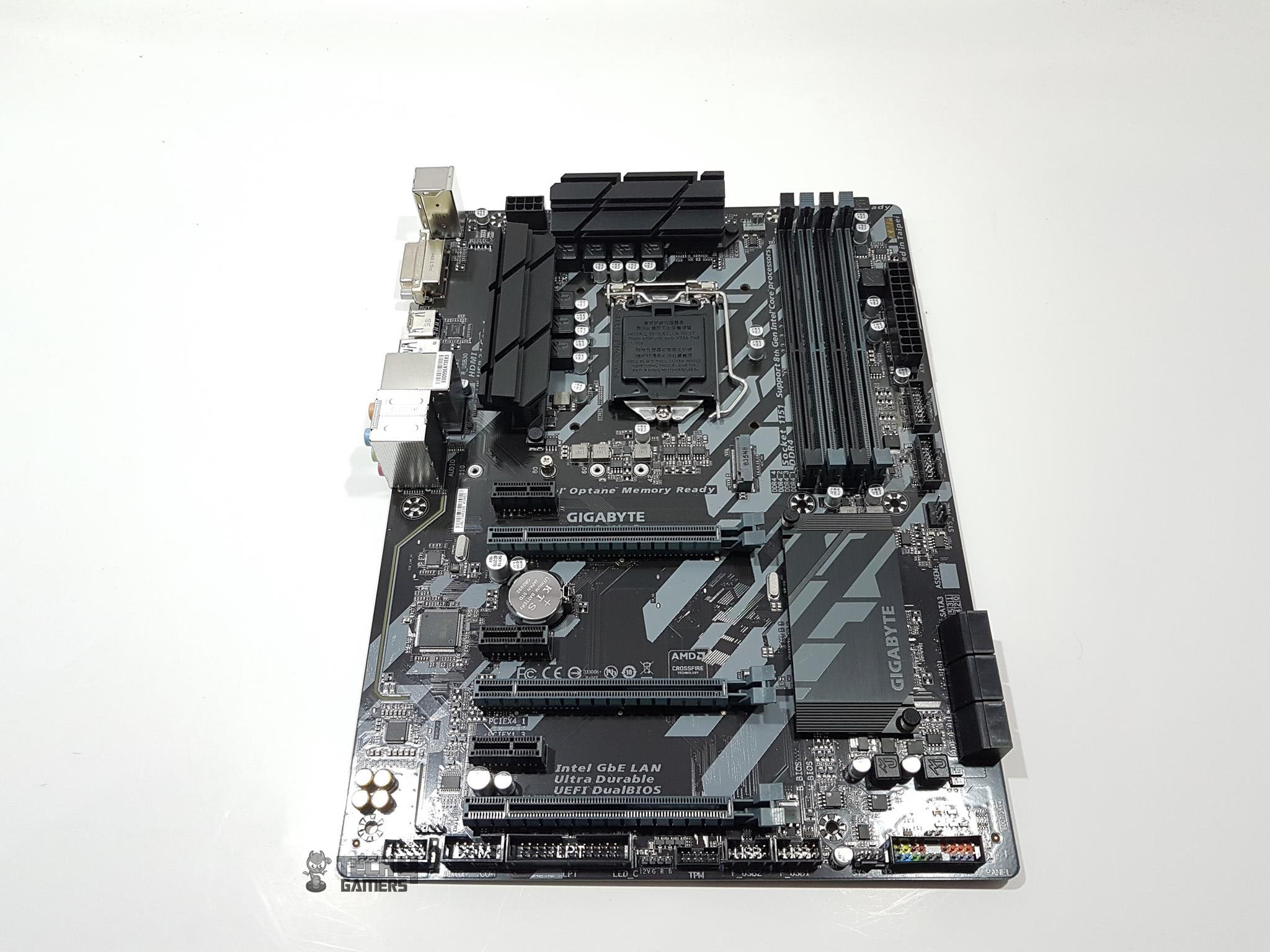
Taking a quick glimpse on the motherboard will give you a gray and black colors combination that has been used on the motherboard. The stenciling is mostly in the gray color which adds a subtle touch to it. There is no I/O shroud which is understandable as this is budget friend motherboard so one can spot the obvious areas from where the cost saving is coming besides the hidden ones. We have 4 DIMM slots for DDR4 memories, 6 PCIe slots, 6 SATA ports, USB 2.0 ports, USB 3.1 Gen 1 ports, onboard sound solution, Intel NIC which is GbE, and nice handy I/O provision through the rear I/O section. We will be taking a closer look on each down the road. We have a new low profile designed chipset cover in gray and black colors pattern which blends in well with the overall layout of the PCB textured pattern and colors. The PCB has ATX form factor measuring 30.5cmX22.5cm and has support for Microsoft Windows 10 x64.
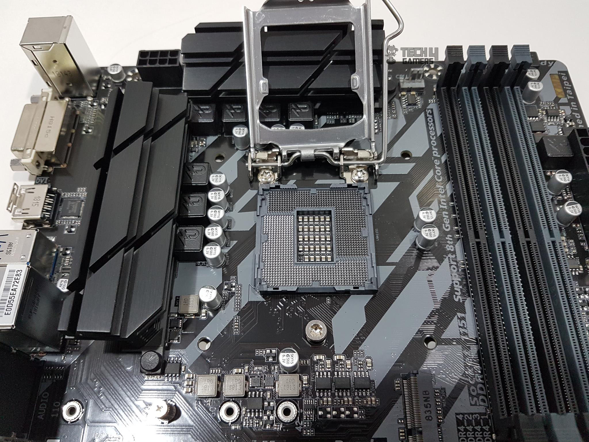
This Gigabyte Ultra Durable Z370 HD3 motherboard has Intel LGA-1151 socket; the same socket which has seen third time a new generation on the same socket albeit the pins configuration changes that locks out the user to use certain generation Intel core processors on the LGA-1151 socket. Skylake (6th gen), Kaby Lake (7th gen), Coffelake (8th gen) and now the 9th generation of Intel Core Processors uses the same LGA-1151 socket but the difference was from Intel Chipset as the Skylake was based on Intel 100 series chipset, Kabylake was based on Intel 200 series chipsets whereas the Coffeelake and 9th gen are based on same 300 series of the chipset. SkyLake and Kaby Lake represent the Intel LGA 1151 revision 1 whereas the Coffee Lake and its successor represents the Intel LGA 1151 revision 2 where the revision 2 is electrically incompatible with the revision 1.
There are 4 pre-drilled mounting holes on the nearby area of the socket. This is for installation of the CPU Cooler. The pathways of wire tracing are quite obvious. Please, take care while handling as tempering these wire traces could easily damage the board beyond repair.
The motherboard has two black color heatsinks covering the VRM and MOSFET area. These heatsinks have cutouts and bearing stepped design making sure that airflow would come handy in keeping the overall temperatures in check. The motherboard seems to be using 4+3 power phases though we could not check for further details like which PWM VRM chip is being employed and if the solution is using doublers or actual phases though, from the looks of it, it seems like there are no doublers.
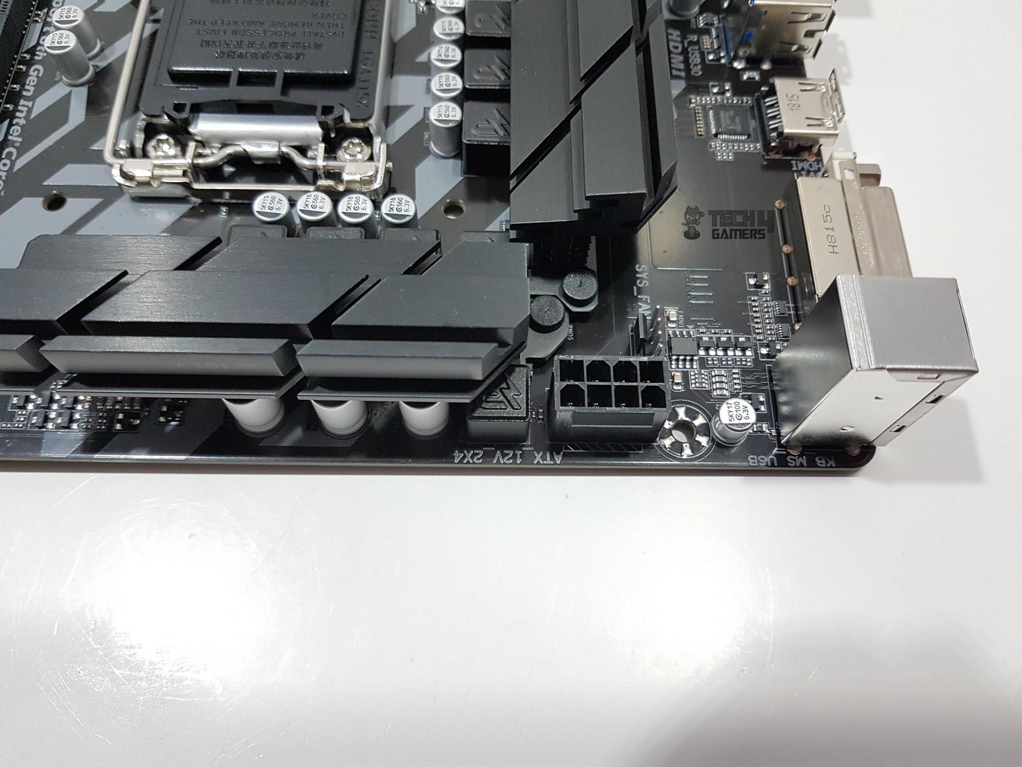
The CPU power connector is located on the top left side which is the standard ATX implementation. There is a system fan header below the 8-pin EPS connector. A single 8-pin EPS connector is enough to provide over 200W to drive the CPU requirements.
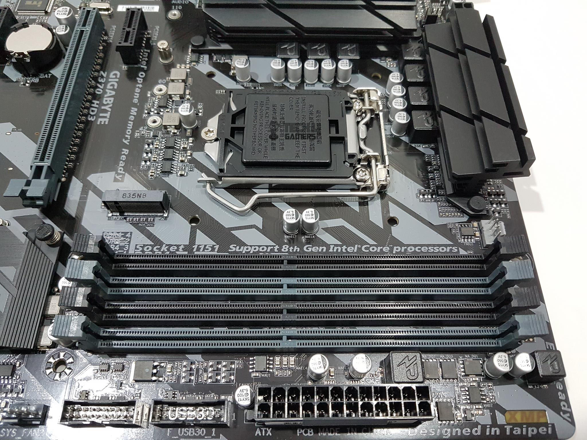
We have a total of 4 DIMM slots in the black and gray colors. For two modules configuration, use the gray color DIMM slots. These slots are not reinforced so take care while handling the RAM. The latches on both ends of the DIMM slots are to be opened to install the RAM which is unlike the typical design these days in which one end is fixed and the other is used to secure the installation of the RAM. The motherboard supports up to 64GB of DDR4 memory with dual channel architecture using ECC un-buffered DIMM 1Rx8/2Rx8 memory modules and Non-ECC un-buffered DIMM 1Rx8/2Rx8/1Rx16 memory modules. The maximum supported speed or frequency on this motherboard is 4000 (OC) which is indeed a better offering from the Gigabyte given the budget nature of the motherboard. As expected, Intel XMP is supported.
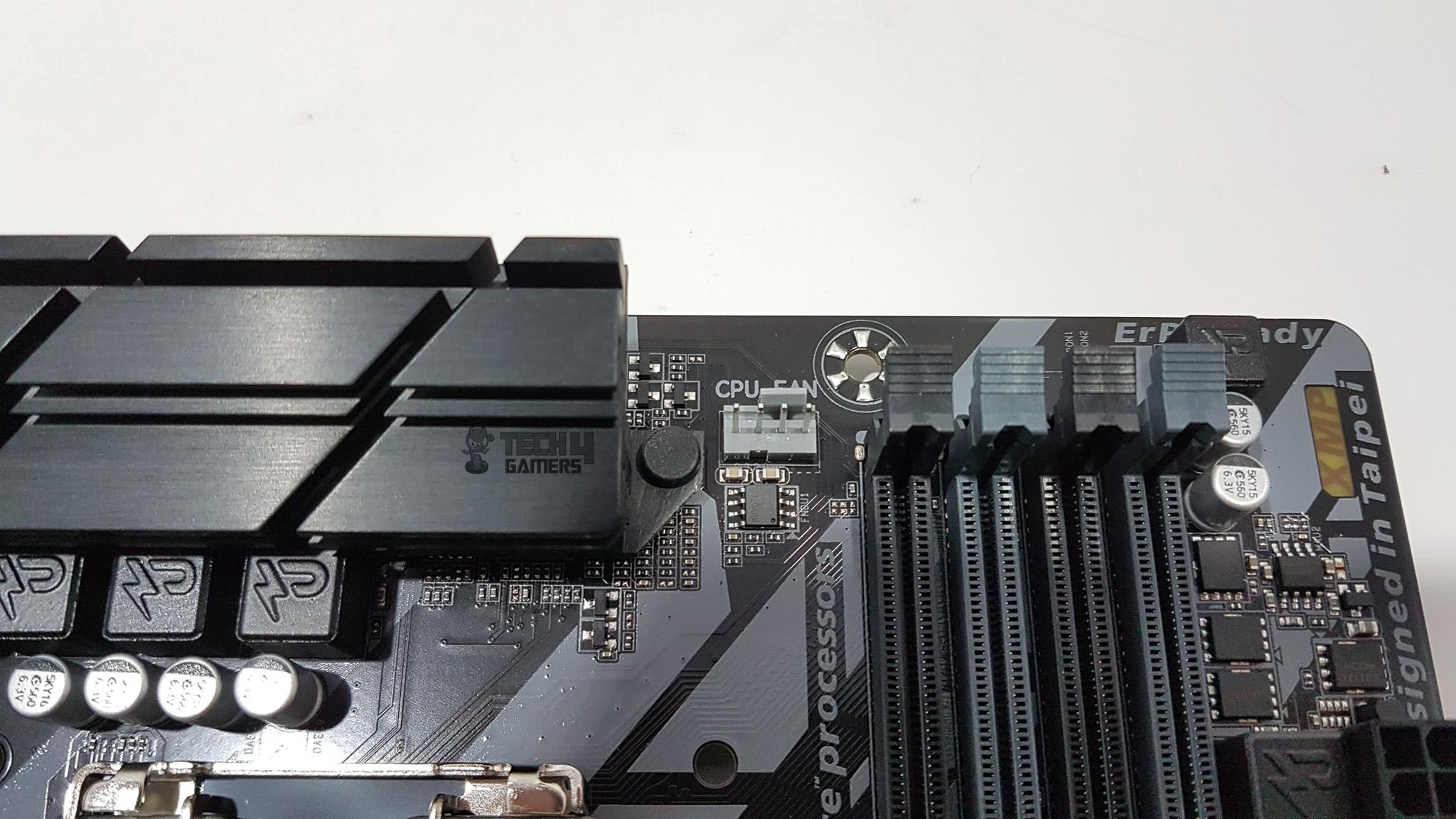
The CPU Fan header is located between the DIMM slots and the CPU socket on the upper side. It is a 4-pin PWM fan header. The Gigabyte uses the terminology of hybrid fan headers under which all the provided fan headers carry 4-pin format and are designed to meet any requirement of AIO Pumps, dedicated Pumps, fans etc.
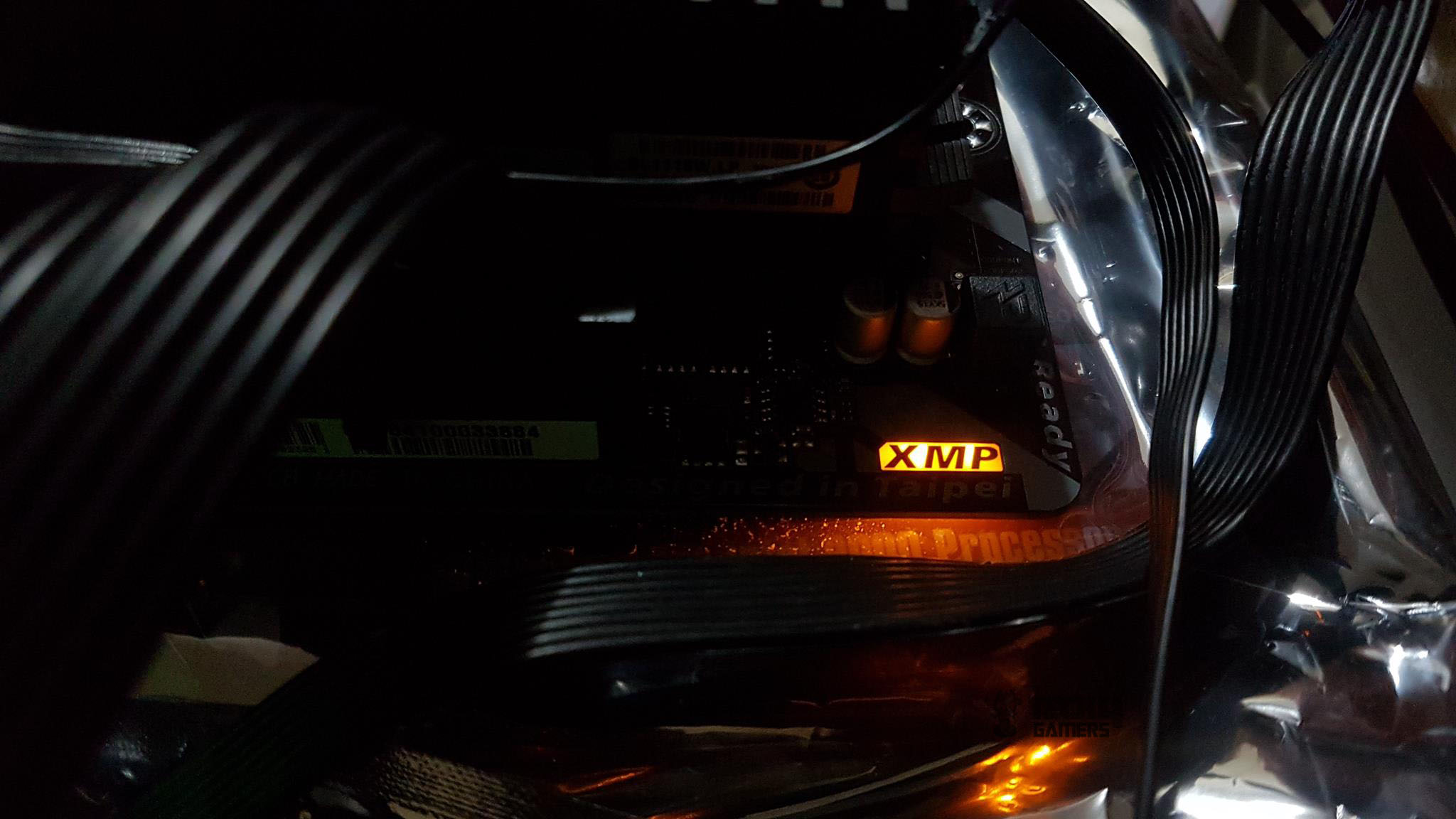
On the rightmost side of the DIMM slots, we have XMP LED which lights up in yellow color to indicate the XMP profile in action. If XMP is not loaded, this LED will not light up. We can’t control the lighting of this LED.
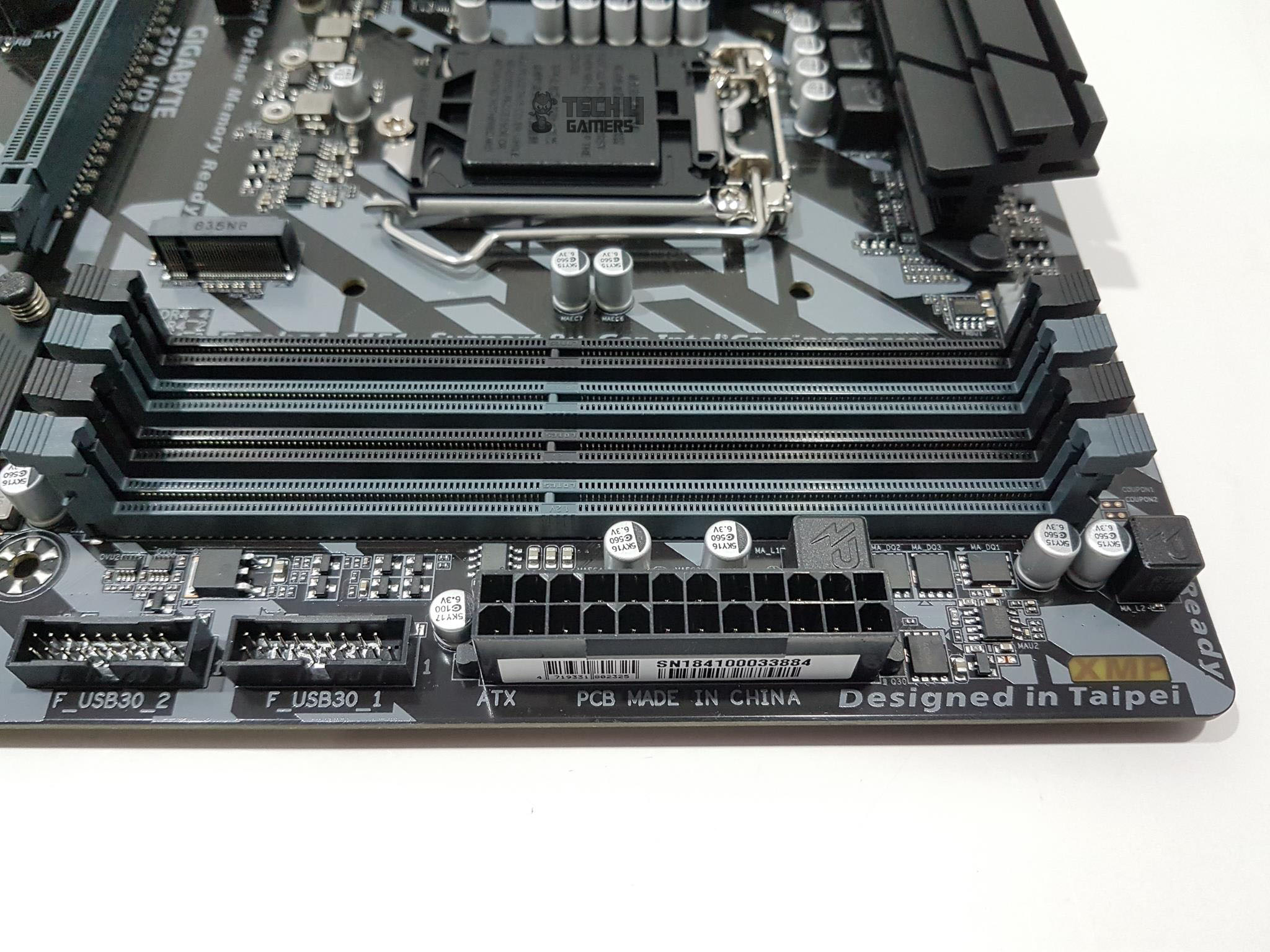
We have a 24 ATX connector located on the right side of the DIMM slots. The PCB of this motherboard is made in China while designed in Taiwan. Going further down, we can see two front panel USB 3.0 headers.
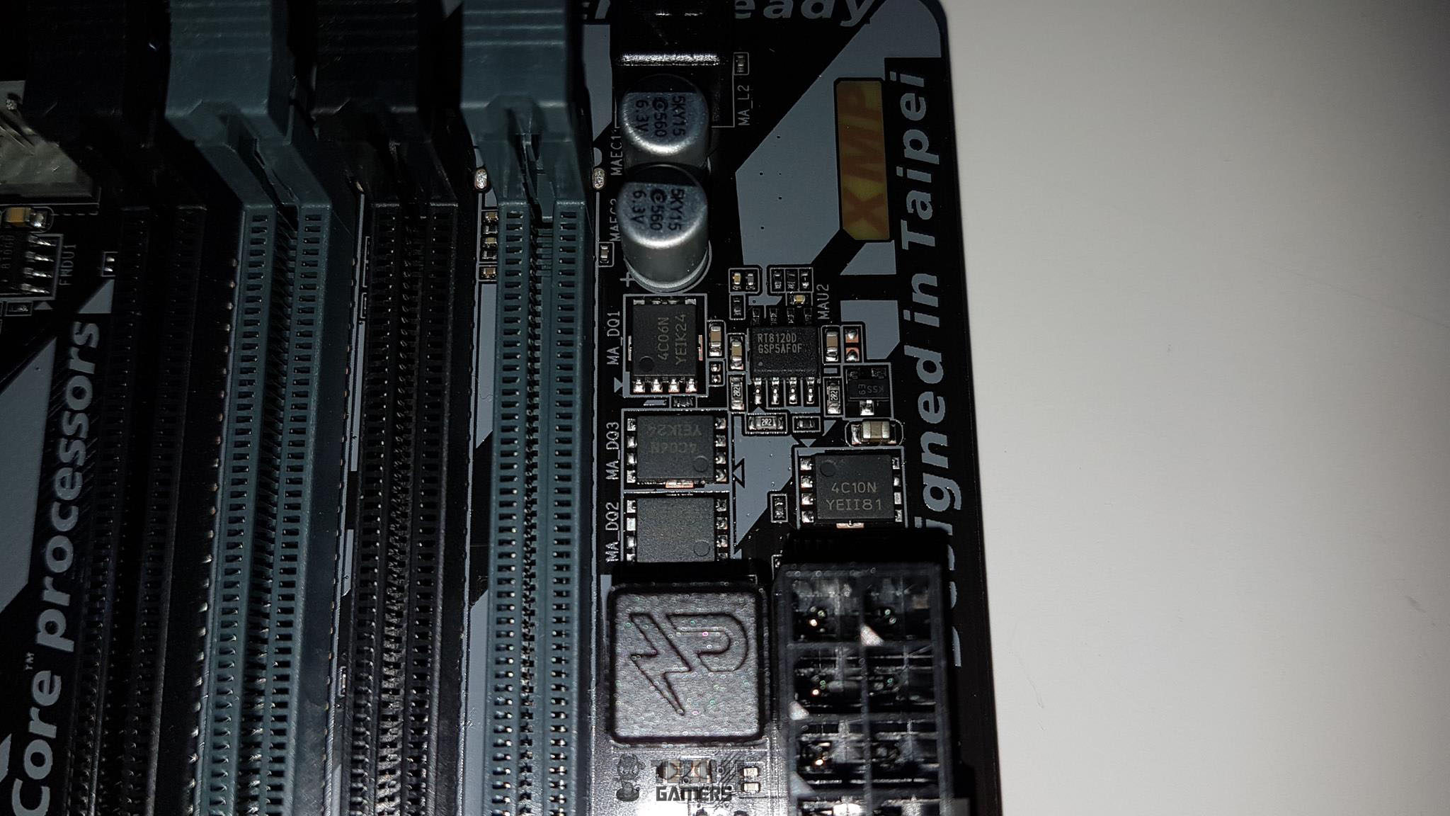
From what we can see on the right side of the DIMM slots there is a Realtek RT8120D for a single phase PWM with a driver. For that, we have MOSFET configuration in the solution of 3 On Semiconductor 4C06N in a two-low one-high.
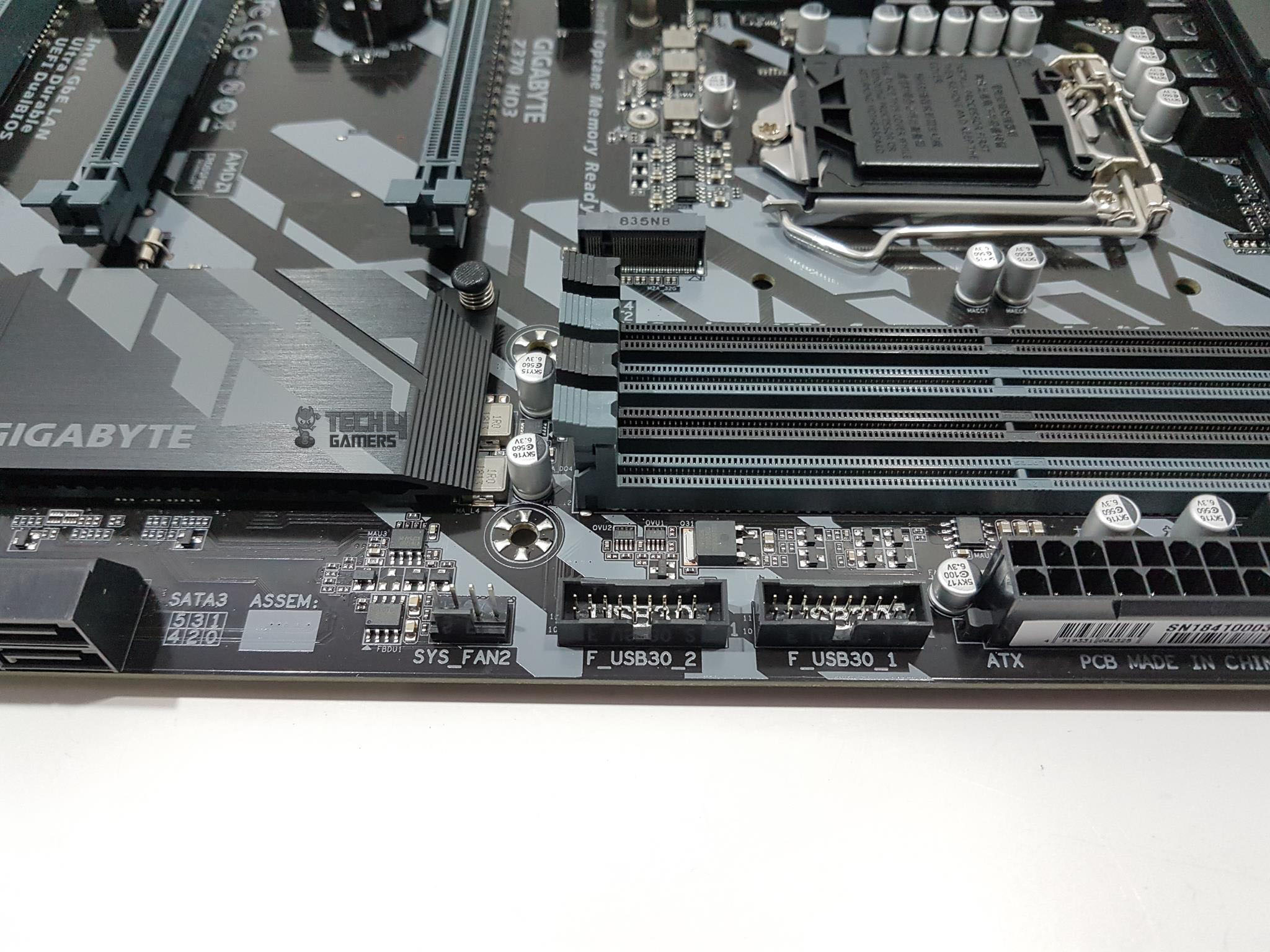
Next, we have another hybrid system fan header labeled System Fan Header 2.
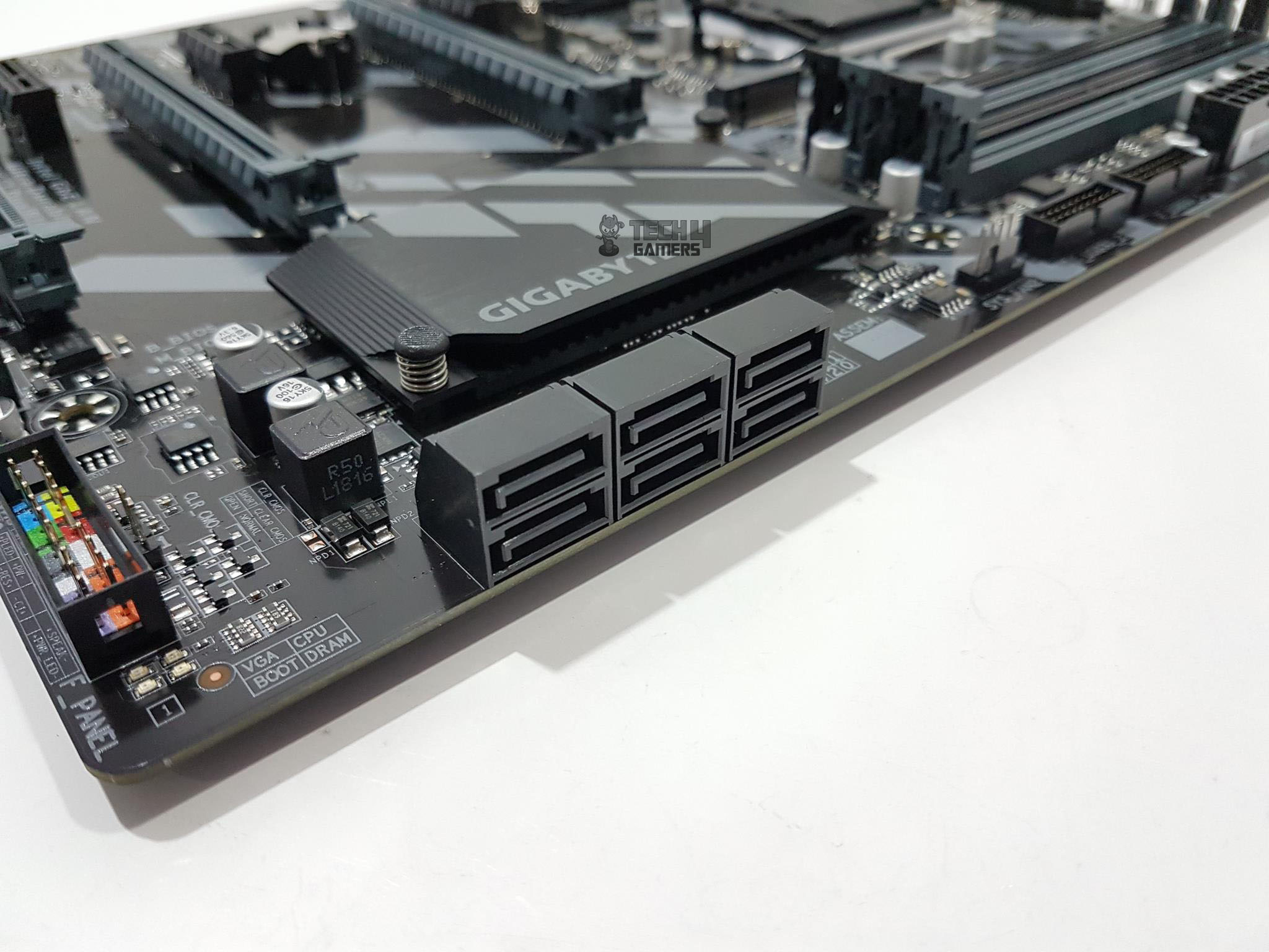
Going further down this line, we have 6 SATA ports rated at 6 Gbps. This motherboard supports RAID 0, RAID 1, RAID 5, and RAID 10. To help the users in setting up the RAID, a dedicated software utility has been provided by the Gigabyte.
Coming further down, we could see a rectangular box with four sections. VGA, CPU, BOOT, DRAM are printed in these sections. Right next to these we have a panel with 4 LEDs. This is the troubleshooting mechanism provided on this motherboard. Each of these 4 LEDs is dedicated to the VGA, CPU, BOOT, and DRAM. In case of any issue or error, the corresponding LED will lit up continuously until the problem is resolved. This makes me wonder if the debug LED is that expensive to implement even on budget boards to provide some real-time troubleshooting help! This is exactly what we have seen on the Asus Strix series of the motherboards. They also don’t have debug LED. But, thankfully, Gigabyte was thoughtful to provide some basic troubleshooting mechanism to help the users out.
Looking at the bottom side of the motherboard, we have system panel connector. The pins have color-coded base for ease of identification and the corresponding configuration is labeled below the connector.
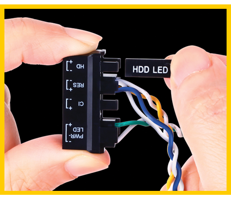
We have seen many users confused over the system panel connector. This is particularly true when it comes to the polarity of the pins and the corresponding jumper and the very small size printing on the PCB owing to the space constraint. Many motherboard manufacturers have started to provide an accessory to ease this situation. All the users would need to do is to connect the PC Chassis’s front panel cables to the provided accessory with the help of clear labels and then just install this accessory on the system panel. Gigabyte has provided G Connector exactly for the same purpose.
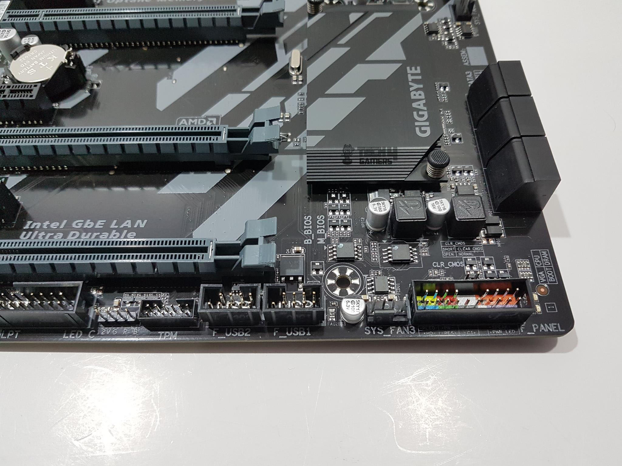
On the left side of the system panel connector, there is another system fan header labeled System Fan Header 3. On its left, we have two 9-pins USB 2.0 connectors followed by 11 pins TPM connector.
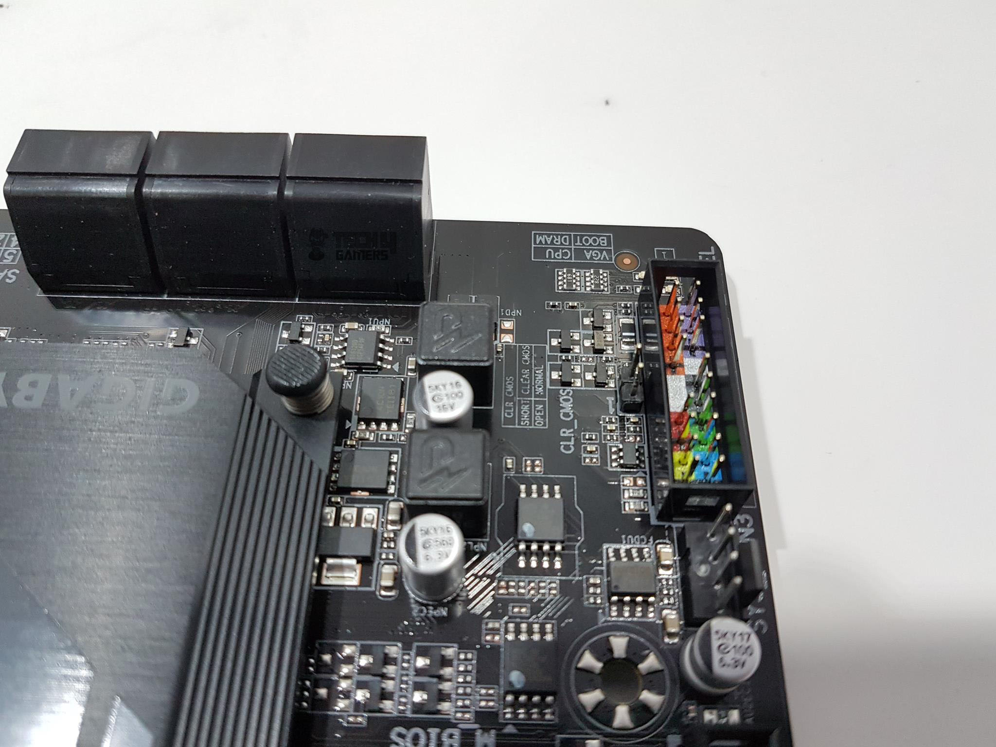
There is a 2-pin jumper right on the top of the system panel connector. This is Clear CMOS jumper. There is no dedicated clear CMOS button on the rear I/O which is understandable. In order to clear the CMOS to reset the settings, shut down the PC, disconnect it from the power source and touch both pins with something like a tip of the screwdriver or by using a jumper if available to short the circuit. Take off the jumper or the screwdriver and power up the PC.
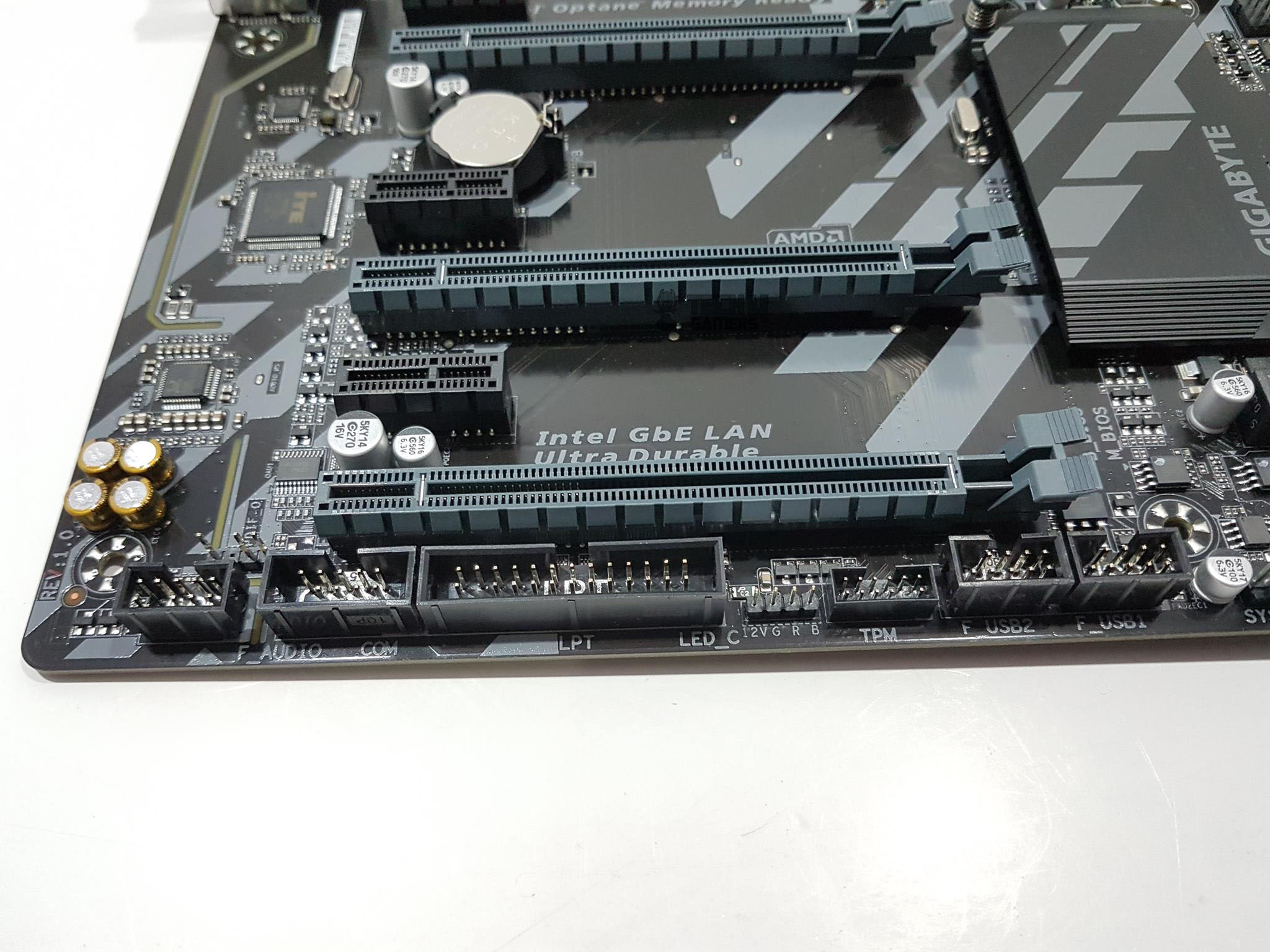
Next, we have 4-pin non-addressable RGB LED lighting connector. It is using the +12V GRB pin format so make sure to connect the supported 5050 RGB LED strip. This header is controlled using the RGB Fusion app. Next, we have 25-pin LPT connector followed by Com port. Seems like Gigabyte is providing backward compatibility for the users who are still using old parallel interface equipment like printers etc. The last connector is the front panel audio one. It is clear that Gigabyte has provided almost all the required connectivity options on this motherboard.
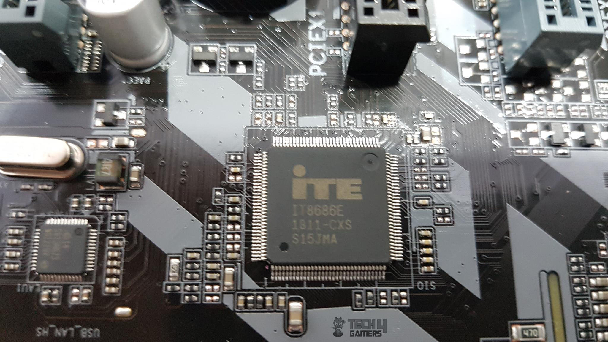
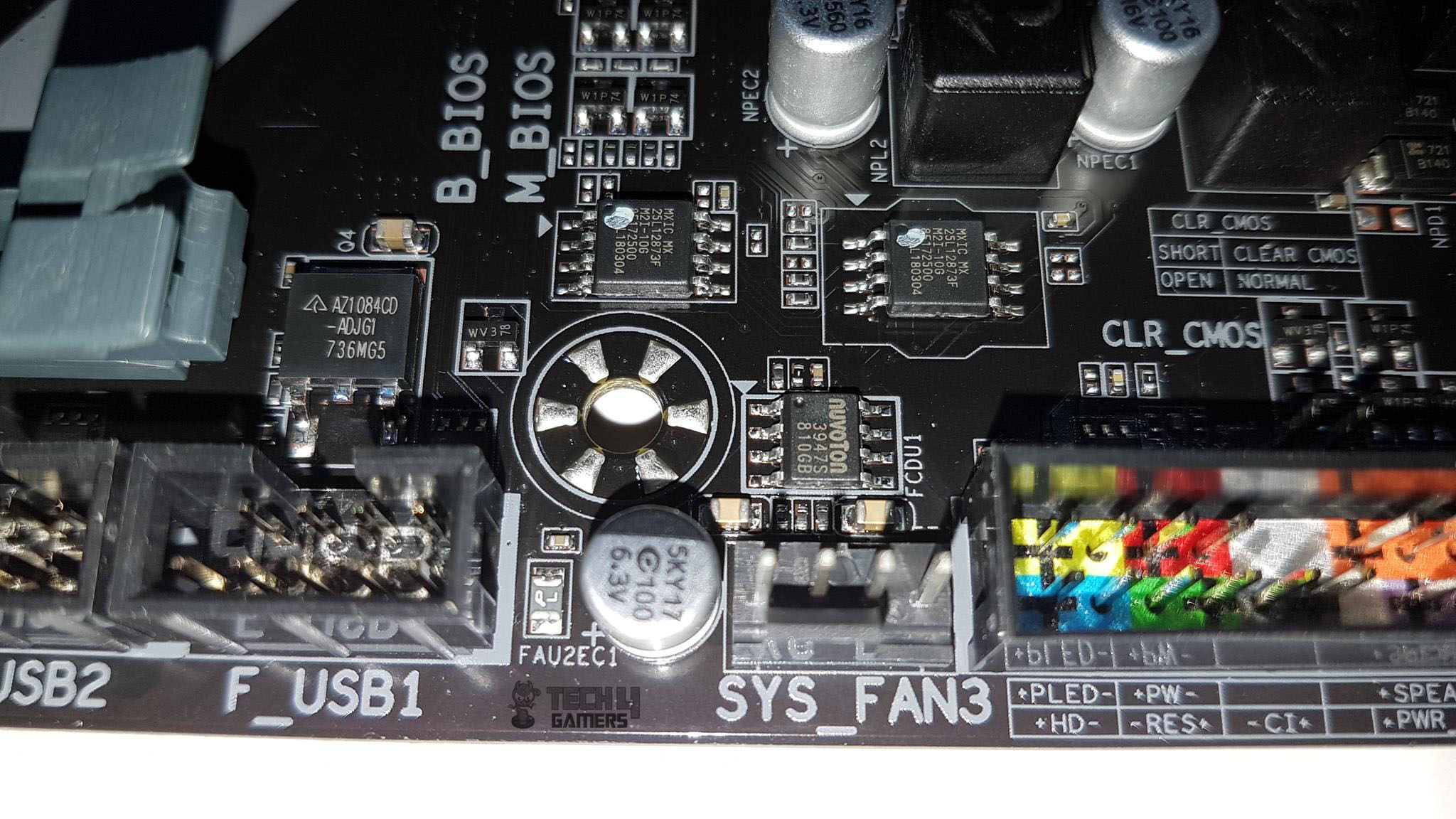
The Gigabyte Ultra Durable Z370 HD3 motherboard is using IT8686E as a main SuperIO controller chip. The Nuvoton 3947S IC is on the board as well which seems to be controlling the fans, and system monitoring.
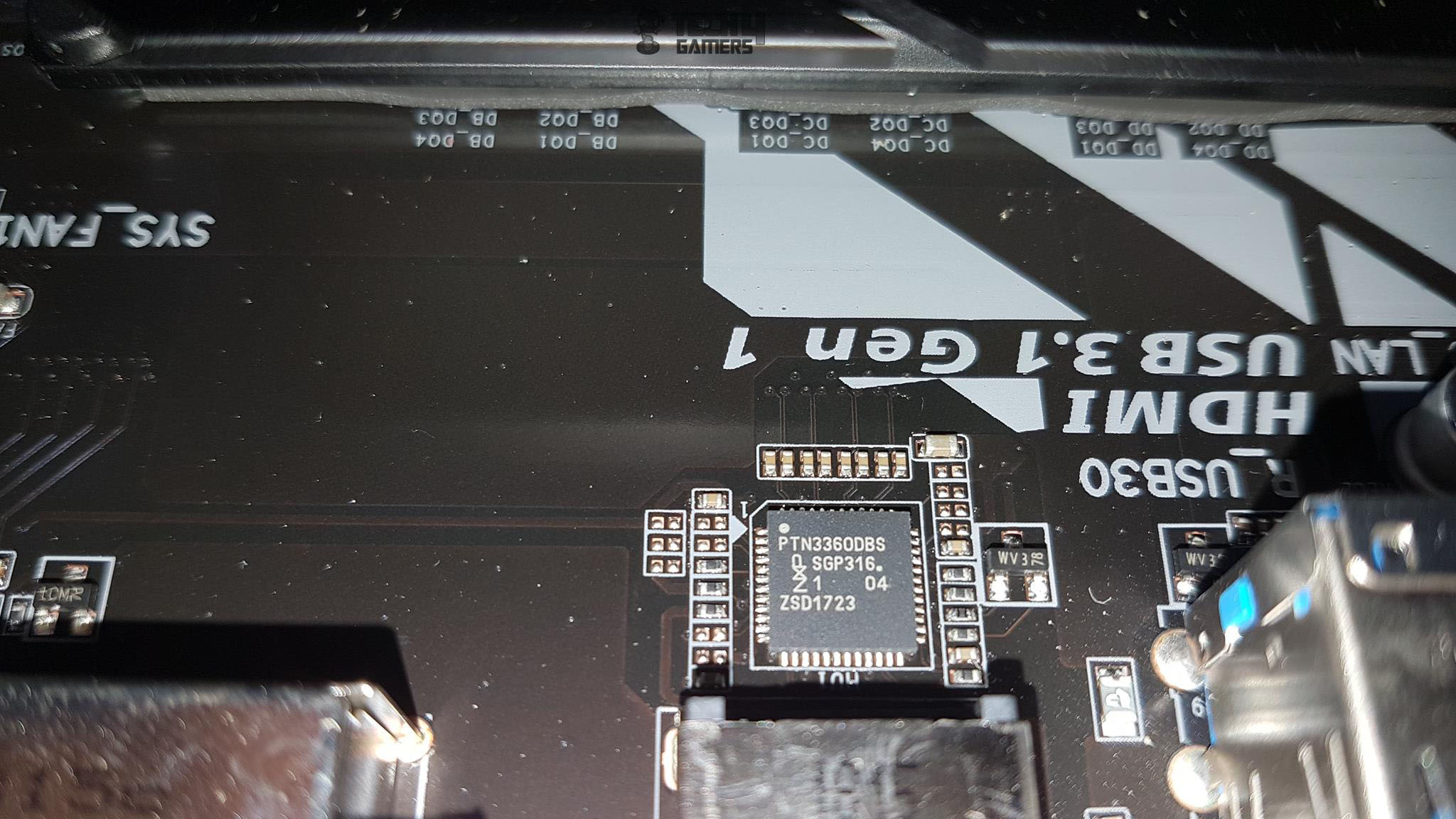
The onboard graphics package includes 1x DVI-D port supporting up to 1920×1200 resolution @ 60Hz (This port does not support D-Sub connection by adapter), and 1x HDMI port supporting a maximum resolution of 4096×2160@30Hz with the support of HDMI version 1.4 and HDCP version 2.2. The maximum of 1GB memory is shared. Gigabyte has provided onboard graphics solution using PTN3360DBS chip. The PTN3360D is a high-speed level shifter device which converts four lanes of low-swing AC-coupled differential input signals to DVI v1.0 and HDMI v1.4b compliant open-drain current-steering differential output signals, up to 3.0 Gbit/s per lane to support 36-bit deep color mode, 4K × 2K video format or 3D video data transport.
USB Ports
This motherboard has 4 USB 3.1 Gen 1 ports on the back panel, 4 USB 3.1 Gen 1 ports through the internal USB headers. We have 2 USB 2.0/1.1 ports on the back panel and 4 USB 2.0/1.1 ports through the internal USB headers. There is no USB 3.1 Gen 2 port on this motherboard which obviously seems to be a cost-saving step.
PCIe Slots
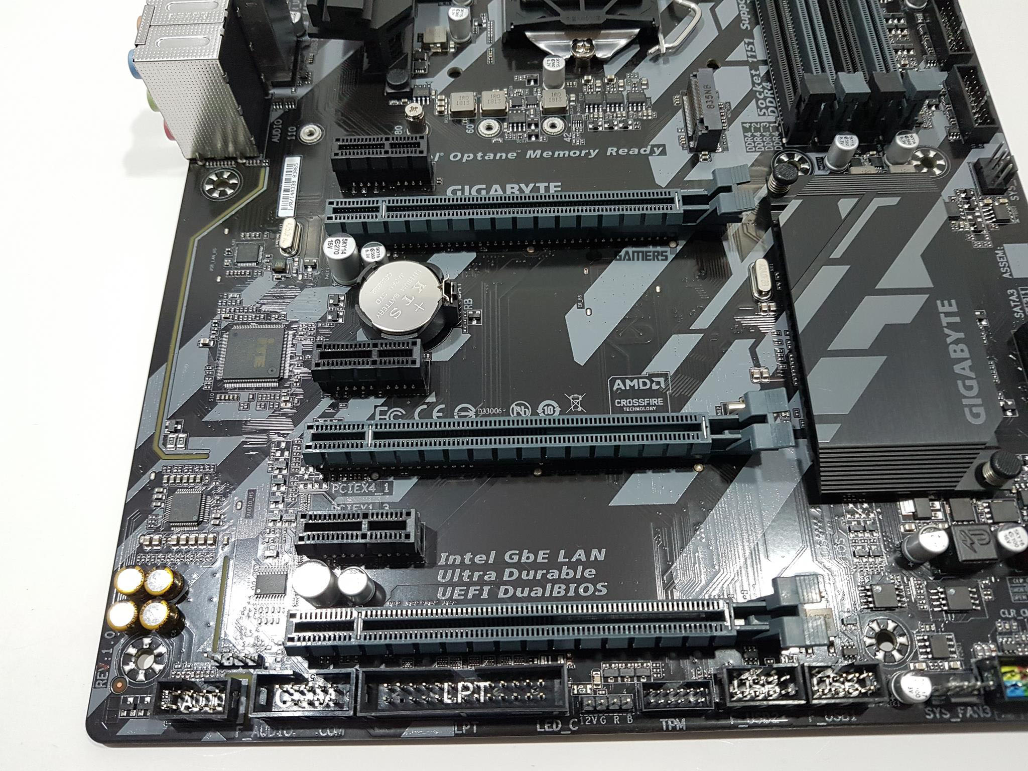
This motherboard has a total 6 PCIe 3.0 rated slots. Three slots are PCIe 3.0 X1 rated. There is only one dedicated PCIe 3.0 X16 slot which is electrically wired to the CPU socket. The other two PCIe 3.0 slots are X4 rated with 2nd slot electrically wired to the CPU socket and the third slot wired to the Chipset. Due to this implementation, this motherboard does not support SLI of Nvidia graphics cards. It does support two-way CrossFire and Quad-GPU CrossFire for AMD graphics cards.
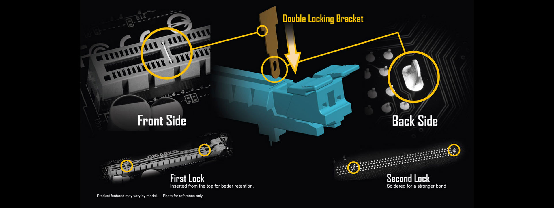
These slots are not reinforced on the outer shell as we are seeing in the modern high-end motherboards where at-least one PCIe X16 slot is steel reinforced. But these brackets feature double locking mechanism; first from the top and the second from the bottom for the better retention.
Audio
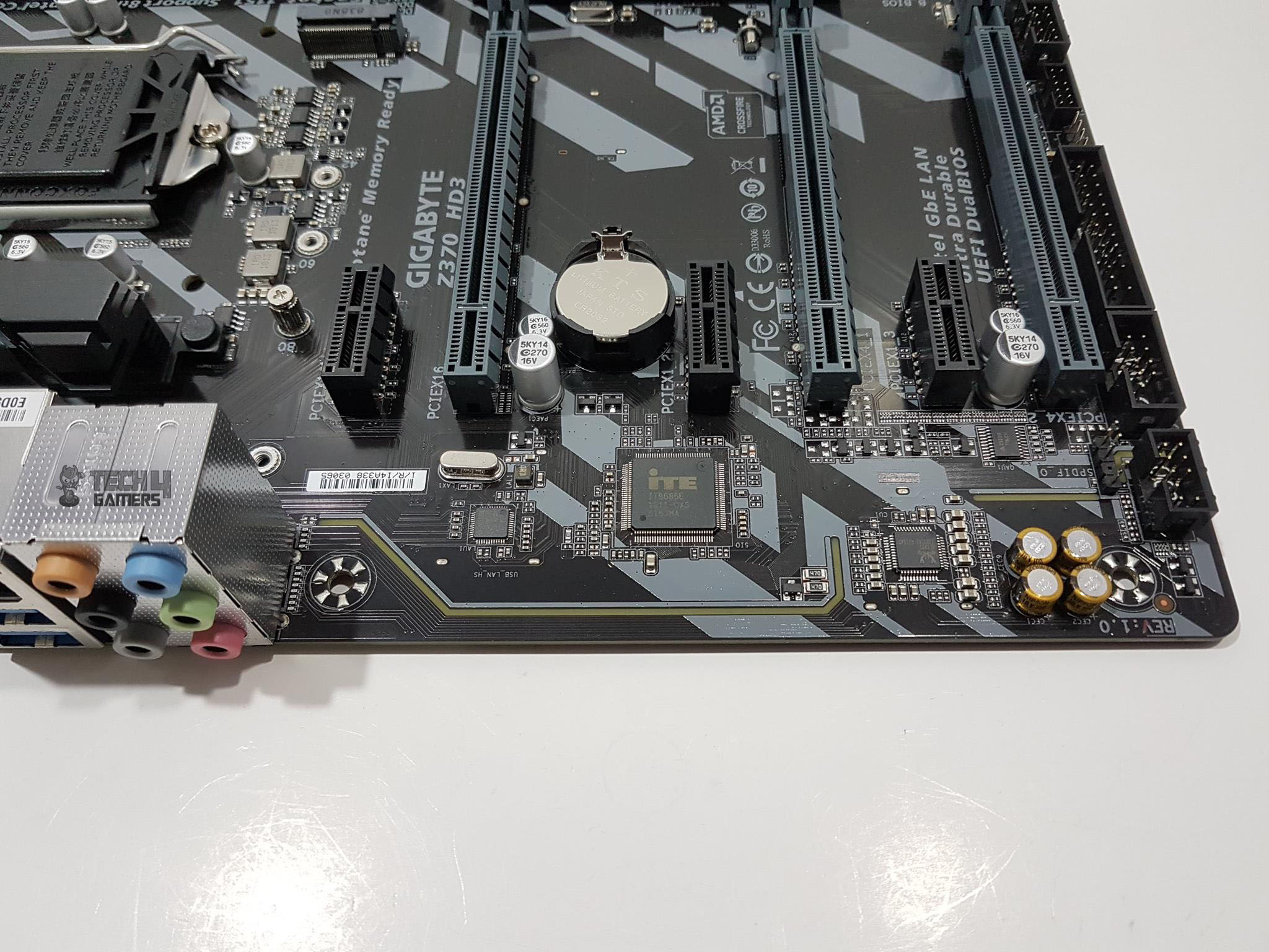
Gigabyte has provided a cutdown version in the onboard audio section as we have Realtek ALC892 Codec supporting high definition audio and 2/4/5.1/7.1 channels. It says to have support for S/PDIF output. The audio section is implemented on a dedicated layered PCB. The audio solution is backed by 4 high-end Nippon Chemi-Con Audio Capacitors. These high-quality capacitors help deliver high resolution and high fidelity audio to provide the most realistic sound effects for gamers. GIGABYTE Z370 motherboards feature an audio noise guard that essentially separates the board’s sensitive analog audio components from potential noise pollution at the PCB level. LED trace path lighting Illuminates to show the separation of the PCB layers.
LAN Connectivity
This motherboard is using Intel NIC which 1 GbE rated with supported speeds of 10/100/1000 Mbit. Intel® GbE LAN features cFosSpeed, a network traffic management application which helps to improve network latency and maintain low ping times to deliver better responsiveness in crowded LAN environments. Clearly, Gigabyte has not ditched out on the high-speed internet connectivity as GbE ports are usually not found on the budget-friendly solutions.
M.2 Port
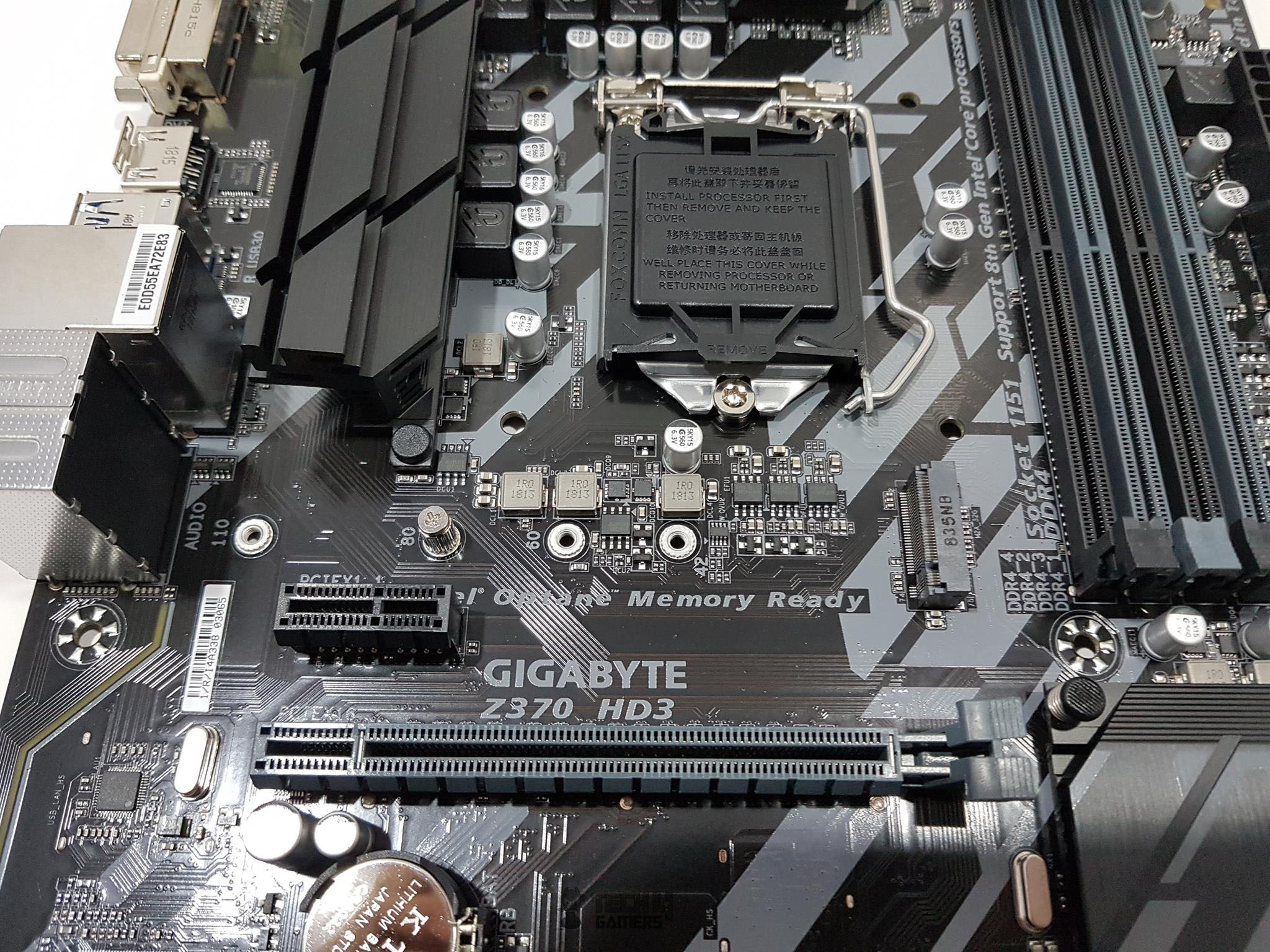
This motherboard has single M.2 port using M Key socket. It has support for M.2 SSDs using SATA/PCIe x4/x2 interface and using 2242/2260/2280/22110 type. Just for information that there is no additional M.2 SSD screw provided in the accessories. The screw is already on the 2280 position nut. The user has to remove it before installing the M.2 SSD and then secure that SSD using the same screw. The user is restricted to a single M.2 port on this motherboard. According to Gigabyte, this port can support up to 32 Gb/s for the NVMe SSD. This motherboard is Intel Optane Memory Ready.
Dual BIOS
GIGABYTE Ultra Durable™ motherboards feature GIGABYTE DualBIOS™, an exclusive (Patented) technology from GIGABYTE that protects arguably one of your PC’s most crucial components, the BIOS. GIGABYTE DualBIOS™ means that your motherboard has both a ‘Main BIOS’ and a ‘Backup BIOS’, protecting users from BIOS failure due to a virus, hardware malfunction, improper OC settings or power failure during the update process. The user can’t update the backup BIOS. This board has 2x 128 Mbit flash using licensed AMI UEFI BIOS. PnP 1.0a, DMI 2.7, WfM 2.0, SM BIOS 2.7, ACPI 5.0 are supported.
Thermal Monitoring and Cooling Solution
Let’s take a peek at what this motherboard offers in terms of the monitoring and cooling solution. This motherboard has 6 thermal sensors installed on various points including chipset, VRM, CPU socket etc. We have 4 hybrid 4-pin fan headers for Fan/Water Pump connectors. Gigabyte has provided an intuitive and user-friendly interface to control these headers and to set them up based on the thermal sensors monitoring. This functionality is offered via SmartFan 5. The user has the option to do so either from the BIOS or using the dedicated app in the Windows. We will cover these in the BIOS and Application sections later in the content. With Smart Fan 5 users can ensure that their gaming PC can maintain its performance while staying cool. Smart Fan 5 allows the users to interchange their fan headers to reflect different thermal sensors at different locations on the motherboard. Not only that, with Smart Fan 5 more hybrid fan headers that support both PWM and Voltage mode fans have been introduced to make the motherboard more liquid cooling friendly. There is another striking feature of the SmartFan 5 which is Fan Stop. With Fan Stop map any fan to stop completely when temperatures drop below a specified threshold. Which fan stops, based on readings from which sensor, and at what temperature—all of it can be customized to your liking. Smart Fan 5 receives up-to-the-second information on flow-rate through the Hybrid Fan Pin Headers—giving you absolute mastery over your PC. All Hybrid Fan Headers can automatically detect the type of cooling device whether it be a fan or pump with different PWM or Voltage mode.
Anti-Sulfur Design with CEC 2019 Ready
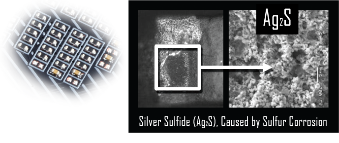
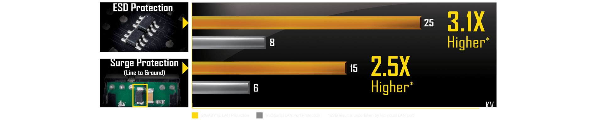
When we talk about Ultra Durable features of the Gigabyte motherboards, the most pertinent feature is the Anti-Sulfur design. Sulfur compounds in the air can penetrate tiny onboard resistors creating chemical change and causing these resistors to open or short. If either of these occurs the motherboard will fail to function. By equipping resistors with an Anti-Sulfur Design GIGABYTE gives Ultra Durable Motherboards a whole new meaning for longevity and durability. The Gigabyte Z370 Motherboards are now ready for CEC 2019! The California Energy Commission (CEC) regulation measures PC systems’ level power consumption. The Z370 Motherboards with selected key components fulfill CEC 2019 power saving requirements hence they are more environment-friendly. We have ESD and Surge protections onboard.
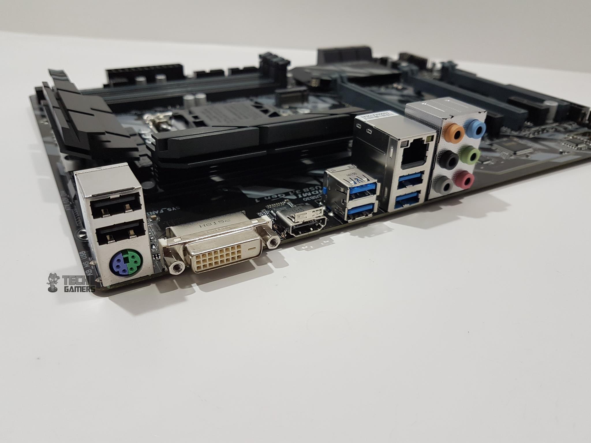
Rear I/O Panel
- 1x PS/2 Port for keyboard/mouse
- 1x DVI-D Port
- 1x HDMI Port
- 4x USB 3.1 Gen 1 Ports
- 2x USB 2.0/1.1 Ports
- 1x RJ45 Port
- 6x Audio Jacks
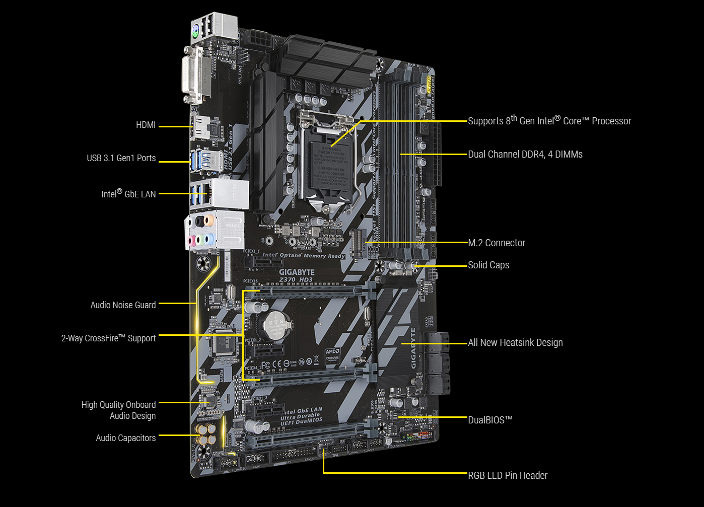
Here is a labeled diagram of the Gigabyte Ultra Durable Z370 HD3 motherboard.
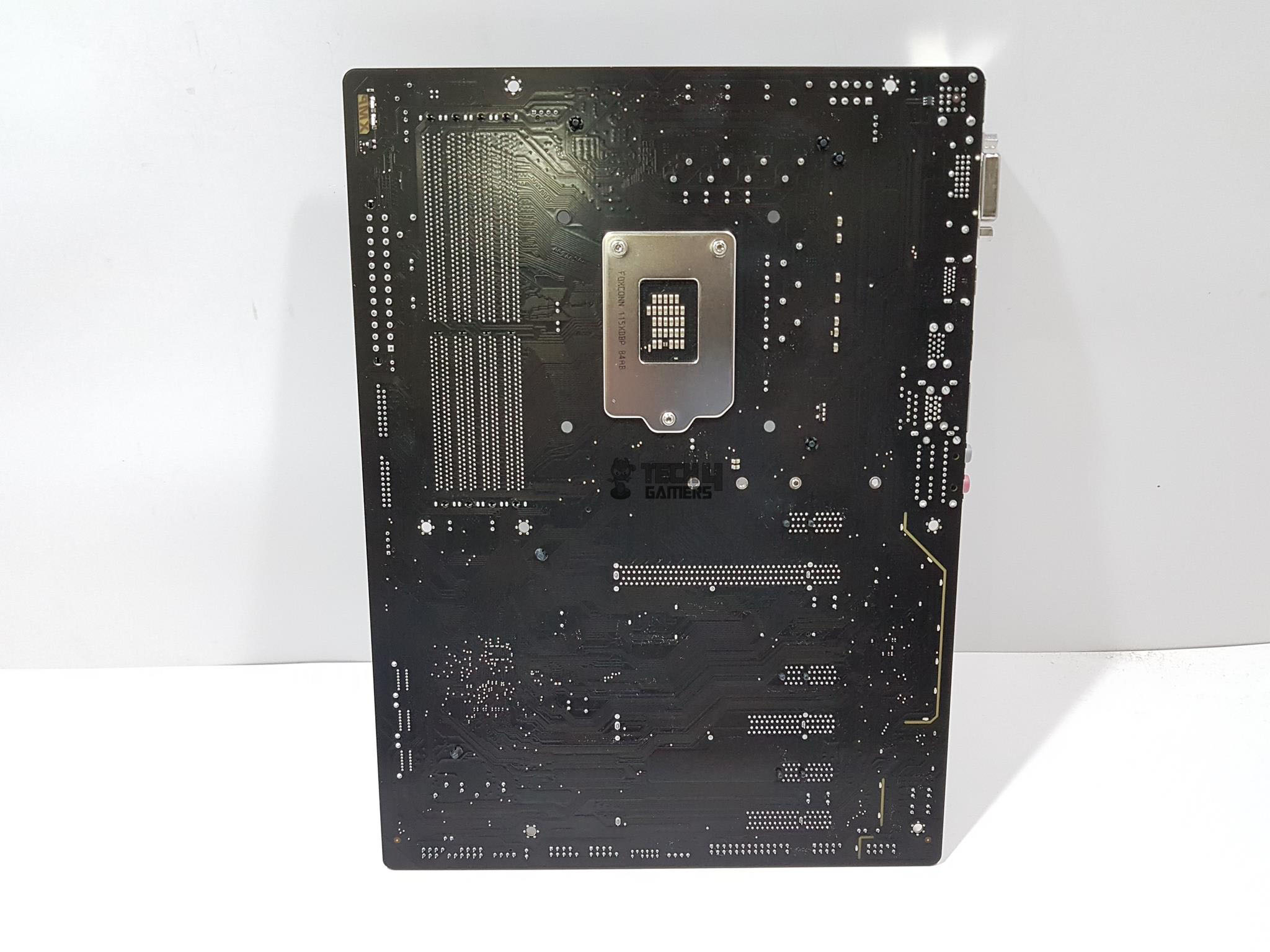
Here is the picture of the motherboard’s backside.
BIOS
BIOS is at the heart of any motherboard and user-friendly BIOS interface is a must. This was our first time with the Gigabyte motherboard and BIOS does not disappoint us. Gigabyte has done a fair job in putting out the UEFI BIOS in terms of its layout and flow. We have black and red colors themed background and interface.

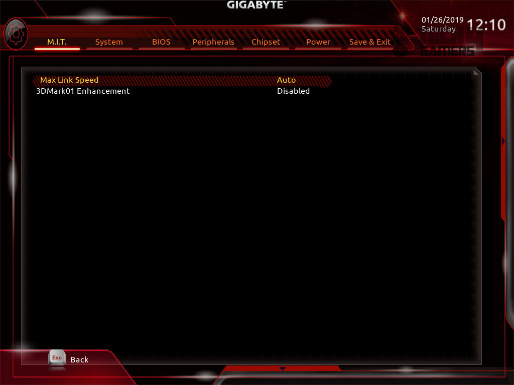
There are two overlay windows that can be shown by hovering the mouse on the rightmost side with arrow indicator and at the bottom right side with the similar arrow indicator. The right side pane shows the summary of the CPU, RAM, and Voltage parameters. The bottom pane shows more navigation options including Easy Mode, Language, Q-Flash and Smart Fan. These are more like shortcuts to the respective page. M.I.T is the main page in the BIOS showing key parameters like Frequency settings, Voltage settings, Memory Settings, PC Health status, and Smart Fan 5 Settings. M.I.T is the main area of consideration when it comes to overclocking the CPU and RAM.
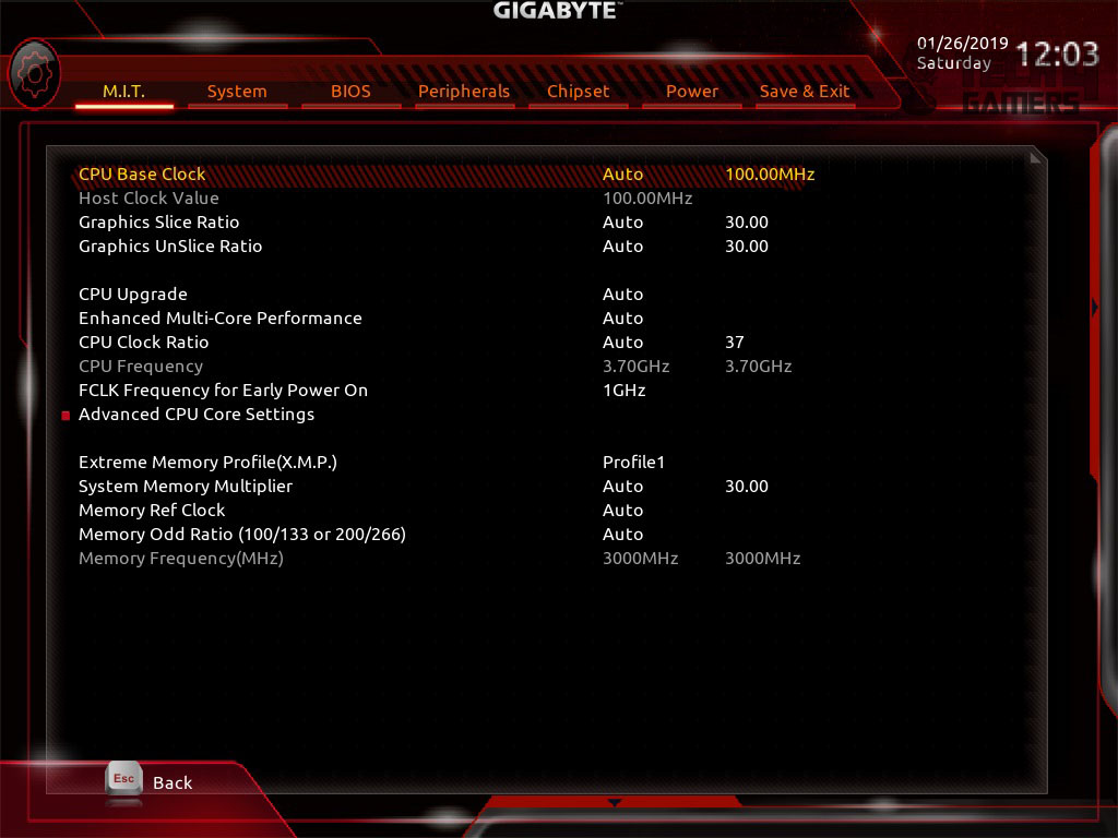
Clicking on Advanced Frequency Settings will load more options relating to the CPU frequency and RAM. XMP can be loaded from this window. To change the CPU Core frequency, simply type in the required frequency in the CPU Frequency parameter. To change the multiplier, CPU Base Clock is there for you.
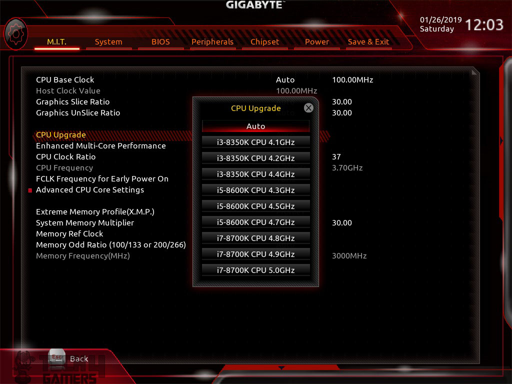
Gigabyte has provided pre-loaded profiles for various CPUs like Intel core i7 8700k and at various clock settings. Each option will load the corresponding settings and all that the user would need to do is to load these settings and save exit the BIOS. That simple!
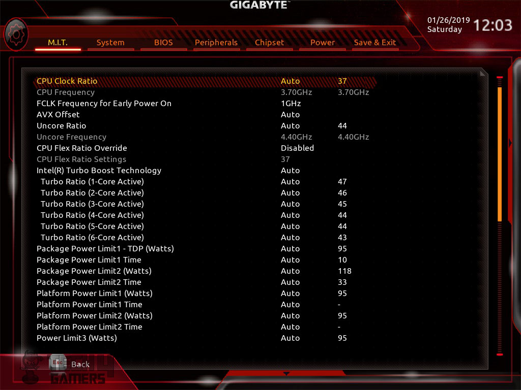
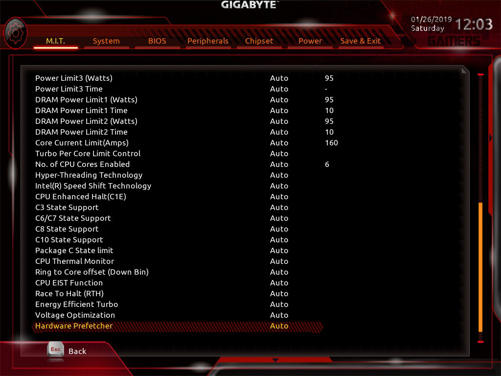
Clicking on Advanced CPU Core Settings will load the new window with a plethora of settings to manipulate the CPU cores. Here you can change the Uncore ratio, AVX offset, disable/enable turbo boost, change individual core’s frequency, manipulate the C states and much more. Make sure to spend your time around to figure out these settings.
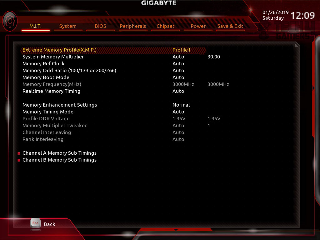
Clicking at the Memory Advanced Settings will load a new window. Here you can load the XMP profile, change the timings of the RAM, change the system memory multiplier, change the memory frequency etc.
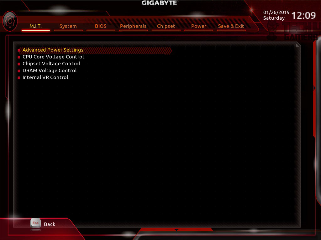
Clicking at the Advanced Voltage Settings will load a new window. This is a sub-menu to control the power of the PC as well as the voltages of the CPU, Memory, Chipset and Internal VR Control. Each setting will lead to further pages with a plethora of options to choose from.
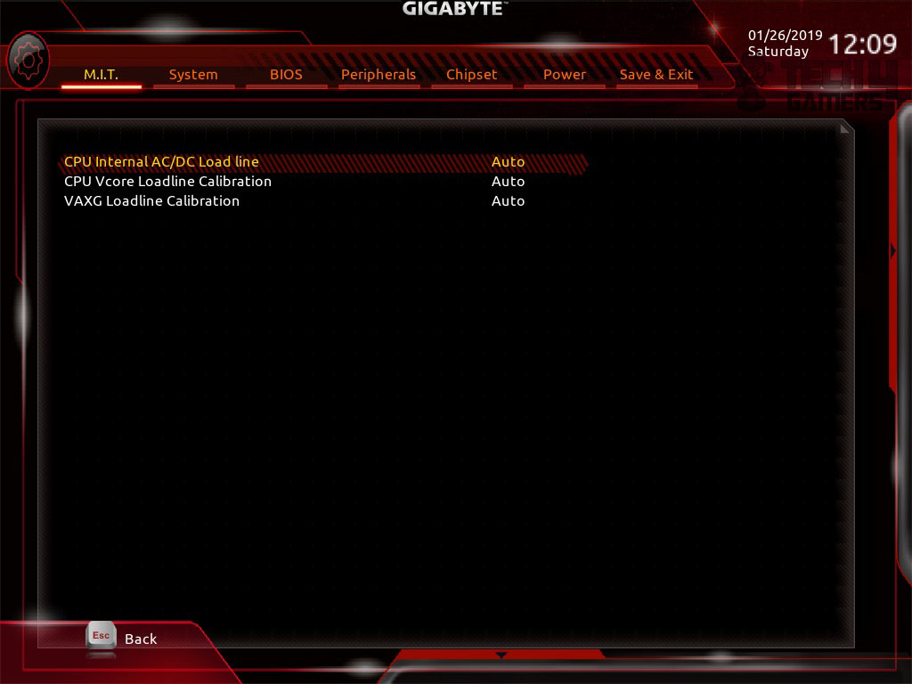
The Load Line Calibration can be accessed by clicking at the Advanced Power Settings.
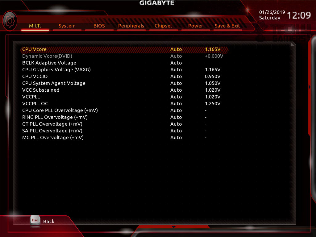
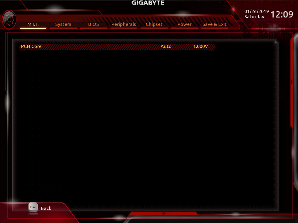
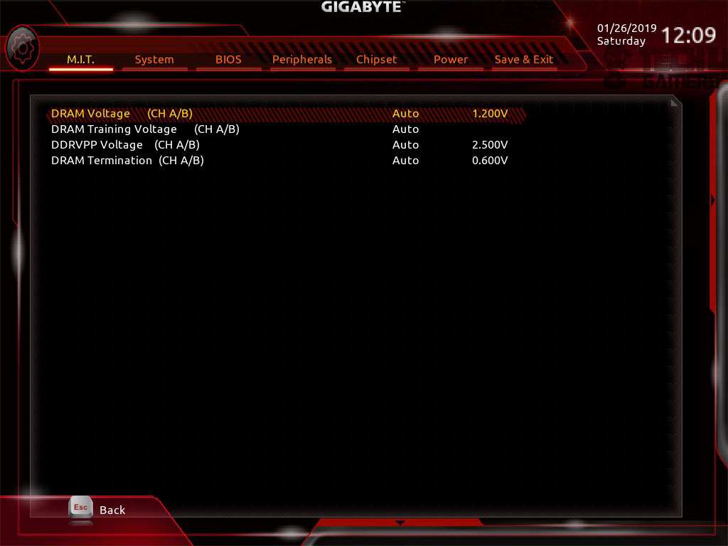
CPU Core Voltage settings are located under the Advanced CPU Voltage settings, Chipset voltage setting can be accessed through Advanced Chipset Voltage setting option and DRAM voltage settings can be accessed through Advanced Memory Voltage settings.
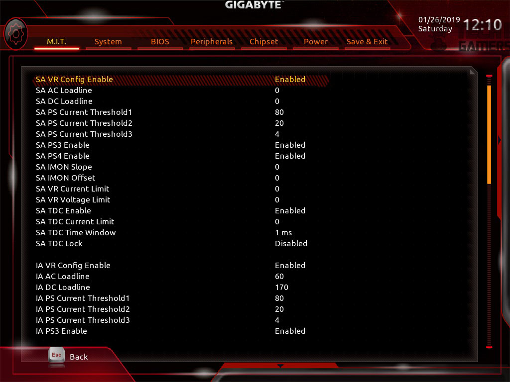
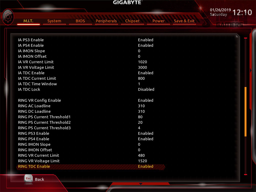
Clicking at Internal VR Control will load a new window for related settings.
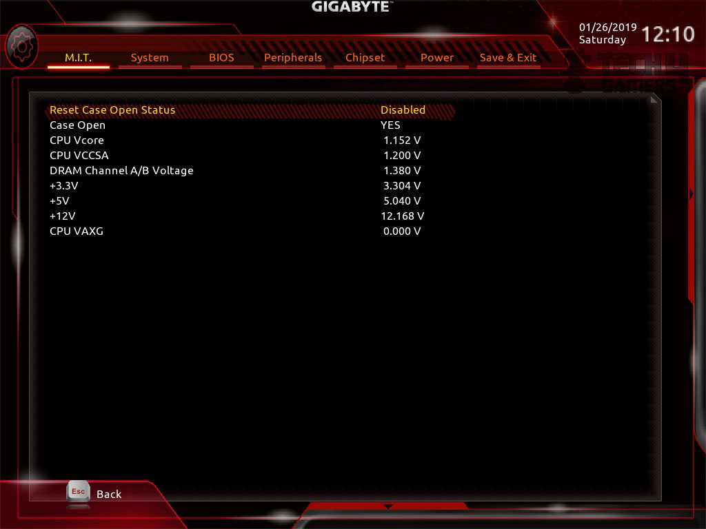
Clicking at PC Health Status will load a new window with a summary of the System and the voltages.
Clicking at Miscellaneous Settings will load a new window with more settings.
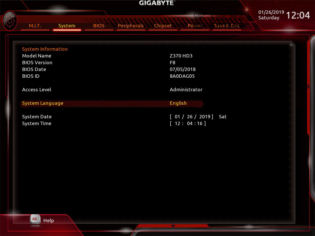
The System tab shows the summary of the system including date and time, language, BIOS version etc.
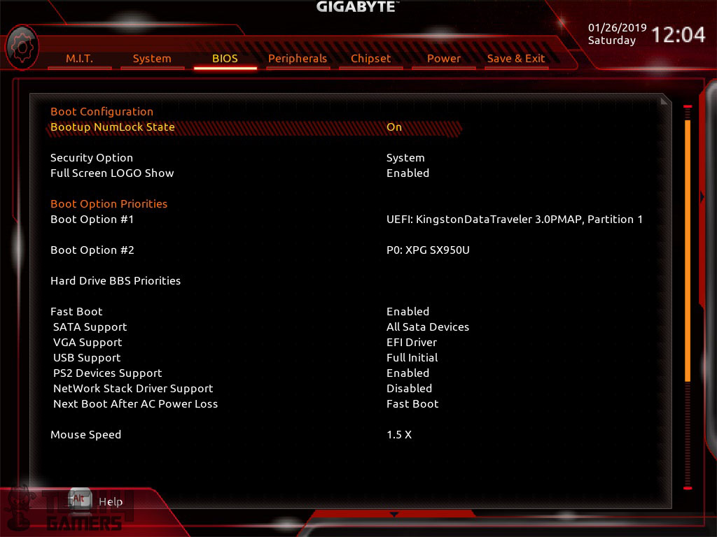
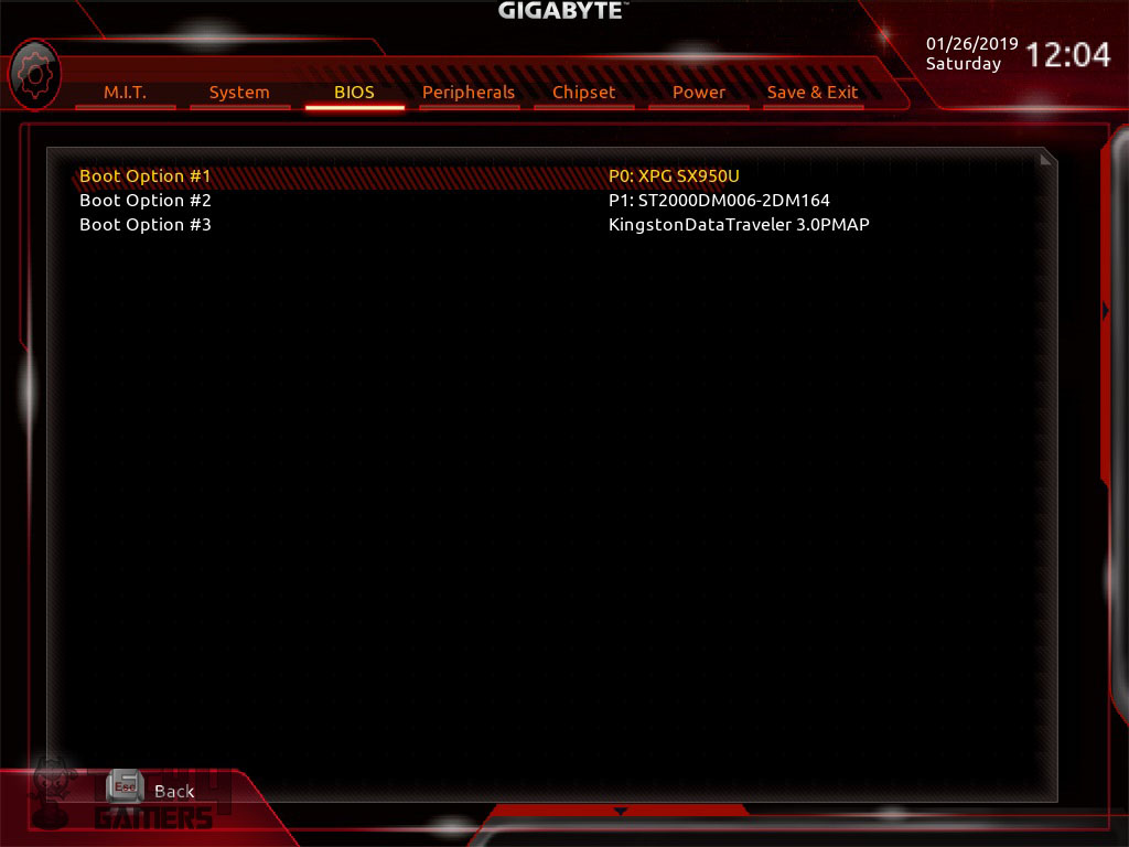
The boot section is named as BIOS which is surprising. The user can set boot option priority as well can set the hard drive BBS priority. Fast Boot can be enabled/disabled from this menu. Mouse speed can also be set right from the BIOS. I set it to 1.5X to my liking. Advanced boot settings an also be found on this page.
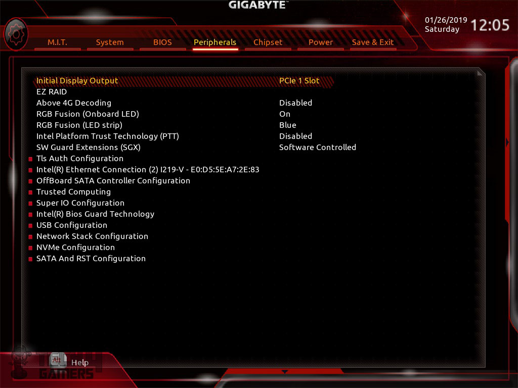
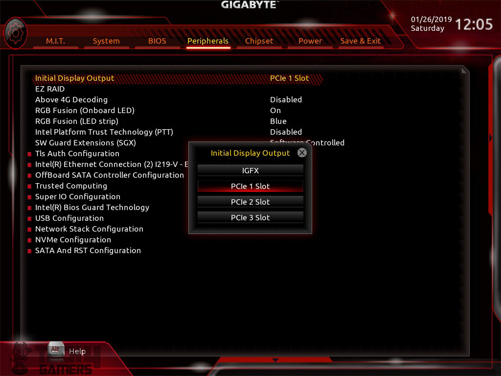
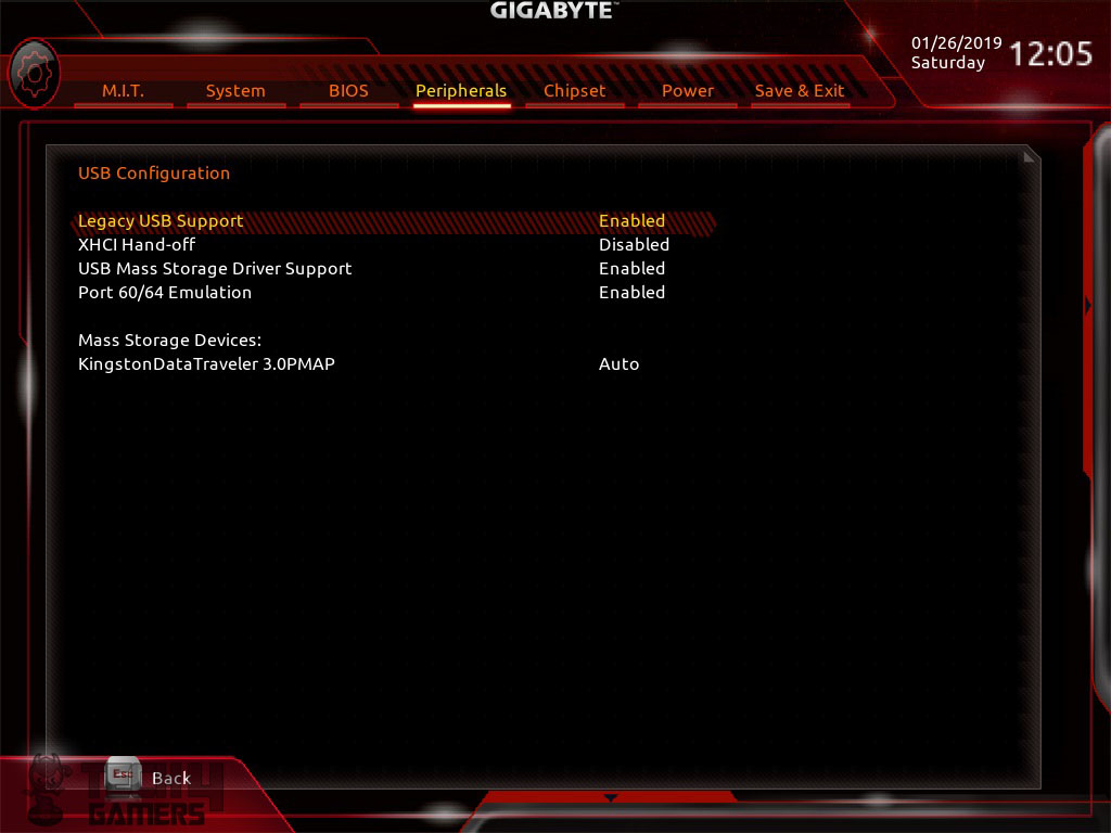
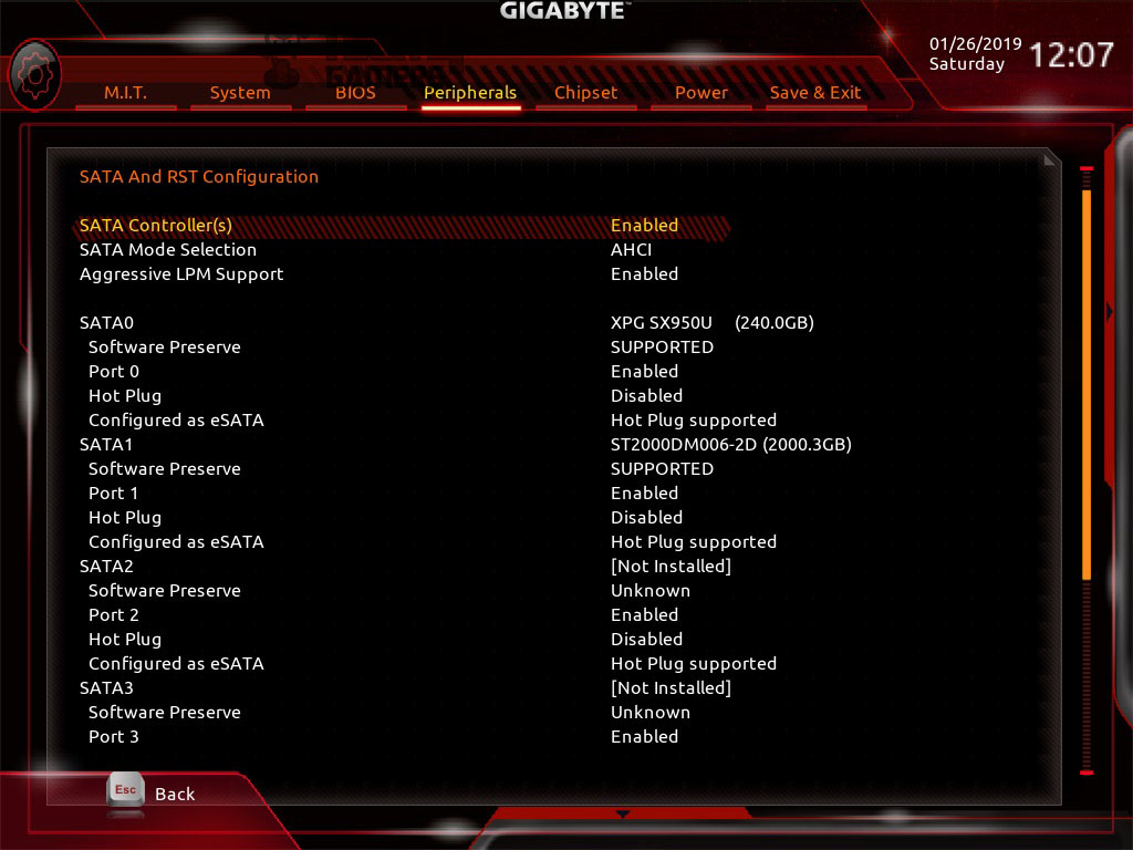
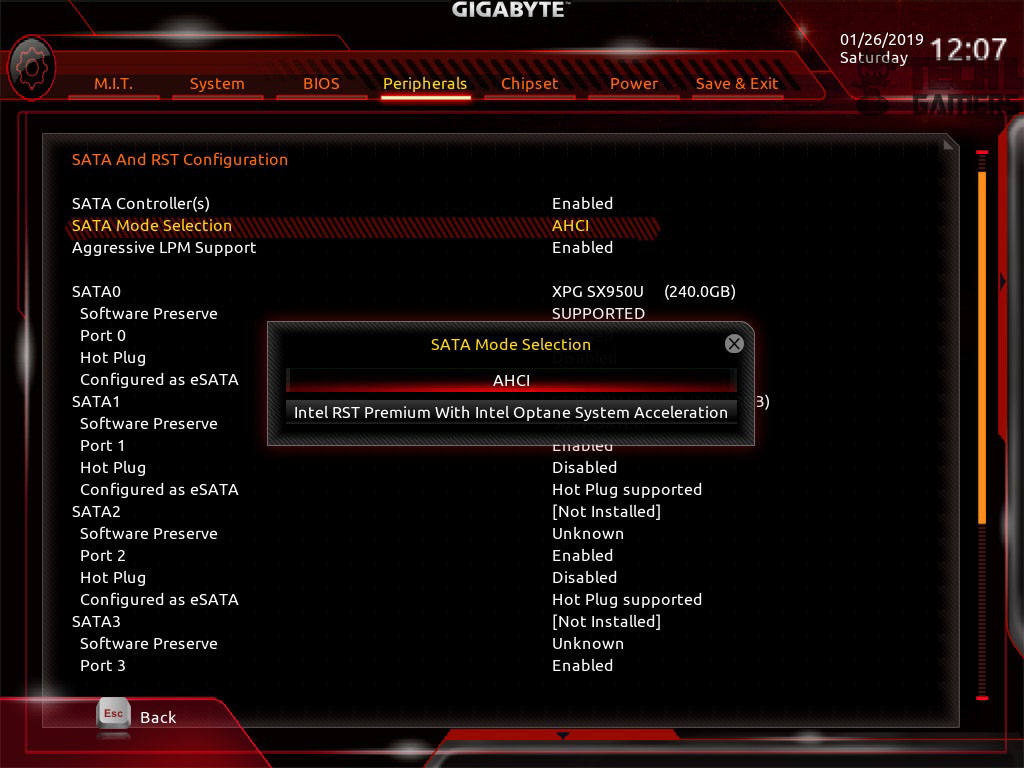
The Peripheral tab shows more options like setting your primary display adapter, RAID settings, setting RGB lighting for the onboard LED (which is static) and setting out of total 7 colors for the RGB Fusion header. Onboard devices can also be controlled from this menu. Intel Optane Memory settings are also in this menu.
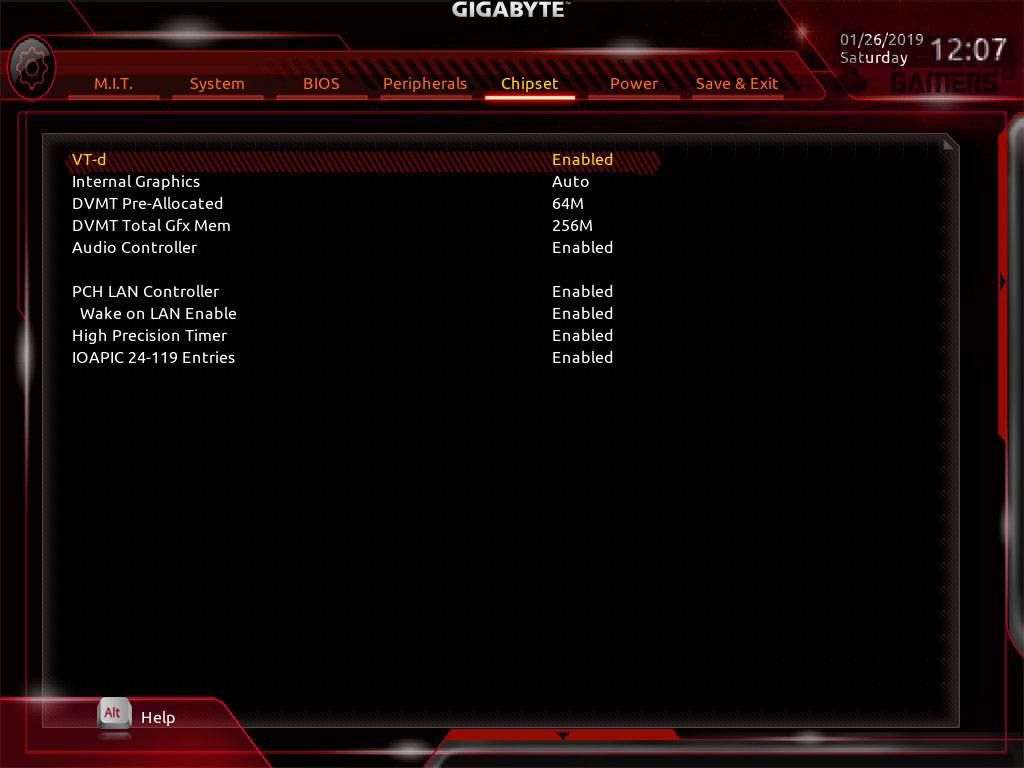
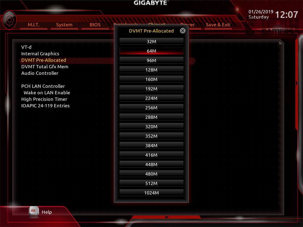
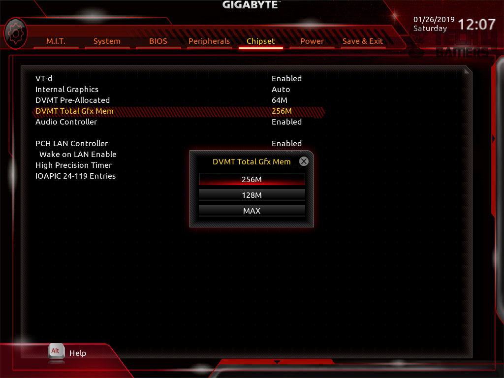
Chipset shows the chipset related settings. The user can allocate the shared memory for the onboard graphics from this menu. A total of 1GB memory can be shared.
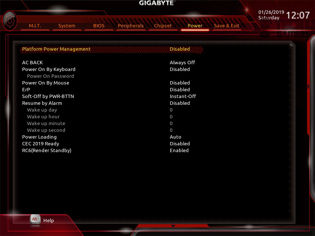
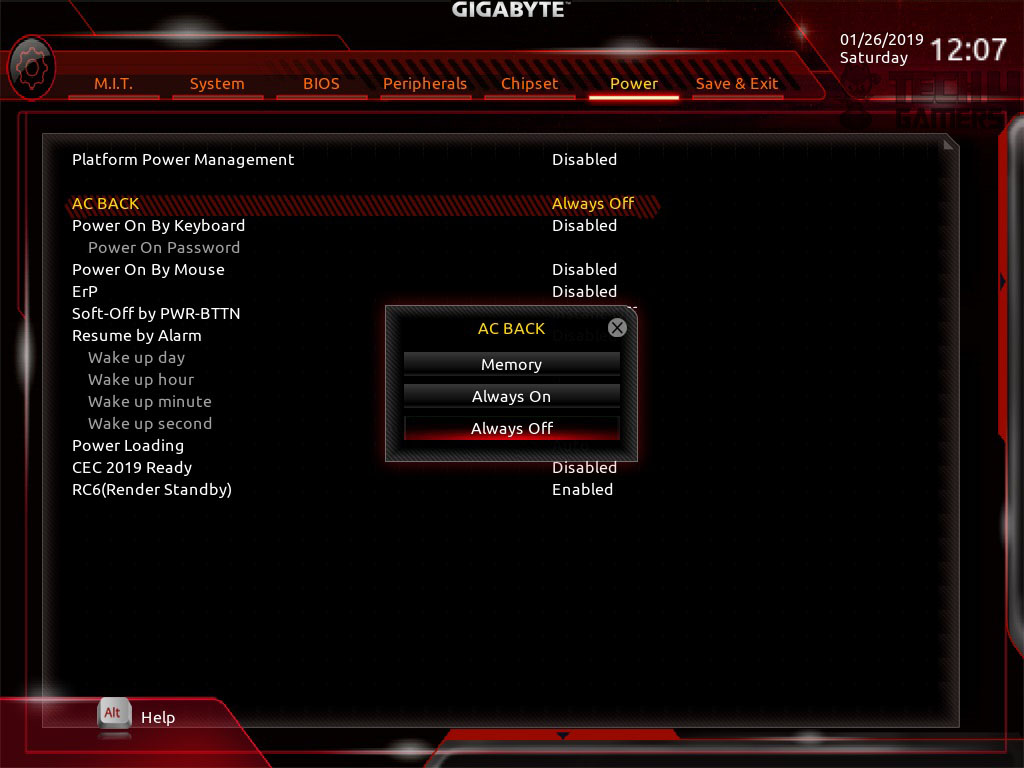
The Power menu has the power-related settings in it. AC Back is the setting that will let you define the settings to decide what to do after the power failure. I set my machines to power on by themselves after power failures.
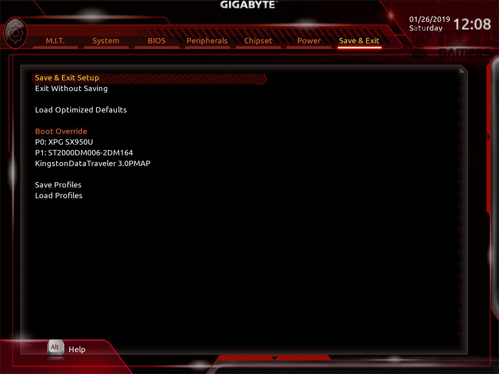
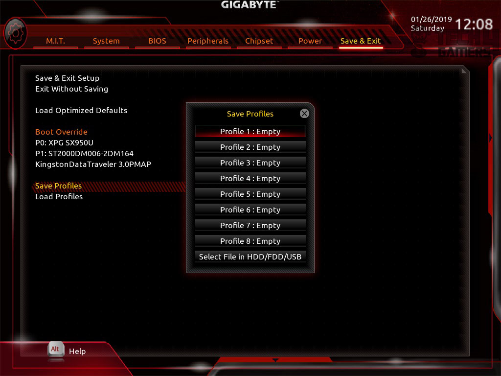
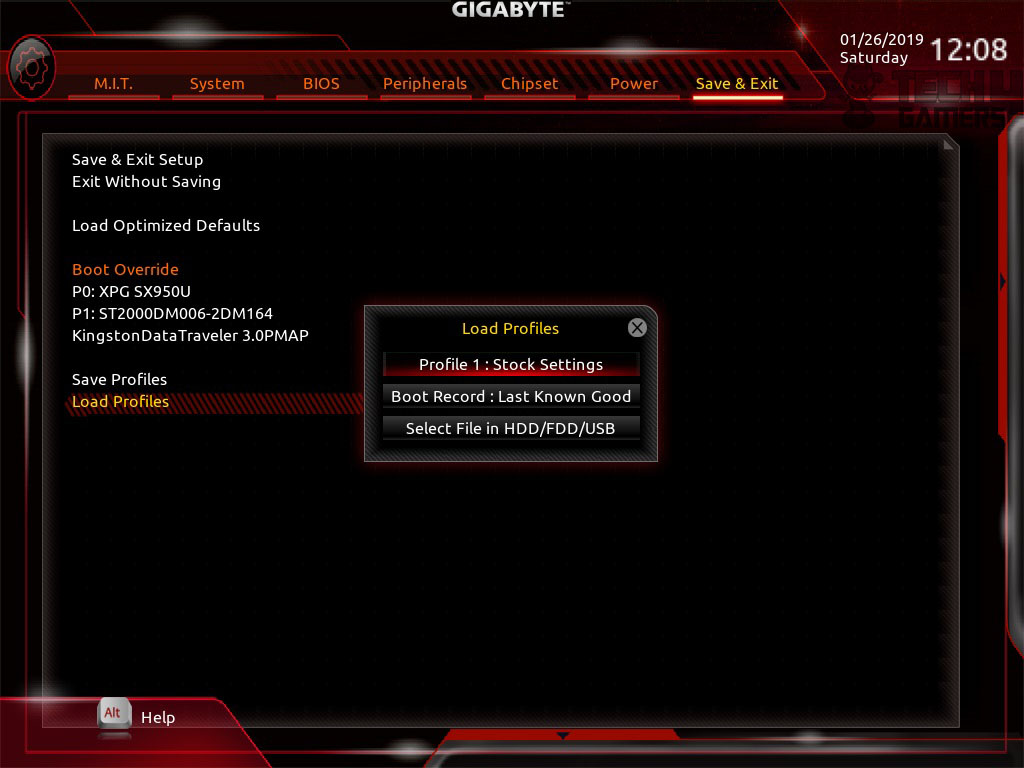
Save and Exit menu has the settings to change your settings and exit the BIOS. It also has the option to let the user save their current settings on to the profiles and to load these profiles in case something goes wrong. This is definitely a handy feature as the user can be saved of redoing all the settings all over again. A total of 8 profiles can be stored. It also allows the user to save/load the profiles in the USB device. This has impressed me.
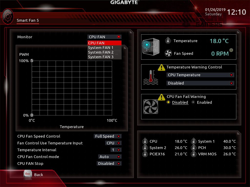
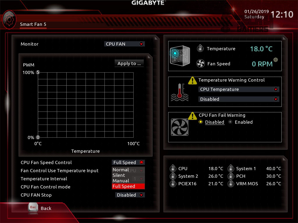
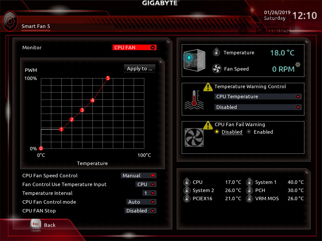
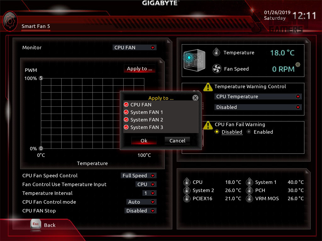
The last option under the M.I.T menu is Smart Fan 5. Clicking on it will load the Smart Fan window. This is the Gigabyte’s way of letting the user exercise total control over their connected fans. The Smart Fan window has two sections. The left section allows the user to control the behavior of the fan while the right section shows the summary of the key cooling parameter. The monitor option shows the fan headers on the motherboard with their names. These names are exactly the same as are printed on the PCB to ease the reference. Select any fan that you would want to control. In the center, there is a graph plotting using two variables Speed (PWM) and Temperature (°C). The Fan Speed Control lets the user select the profiles like Full speed, silent, Normal, and Manual. Selecting Manual will allow the user to plot the graph according to the required custom fan curve. The user also has to option to source the speed control according to one of the 6 thermal sensors on this motherboard. The user can also set the fan to be stopped (excluding the CPU Fan) based on the thermal criteria. The user can also define the alarms based on the temperatures. Settings are flexible enough to let the user apply the same settings on more than one fan headers. This will save them precious time.
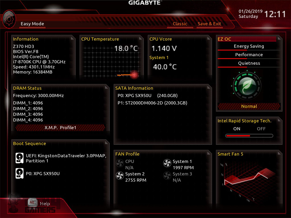
By default, the Classis mode (Advanced Mode) is loaded in the BIOS. The user can switch to the Ease mode. The Easy mode has a more easy and understandable layout for the critical information presentation like key voltages, temperature zones, connected fans and their speeds, connected drives, 3D graphical presentation of the fan speed. The user can load Performance, Energy Saving, and Quietness mode for the system.
Software
Having discussed the BIOS, it is time to take a look at some of their applications that are available to be downloaded from their website. The main software is called App Center. It is a must requirement before installing any of their other applications. This application will install a few other services that are needed for the complete suite’s optimal working. We will be taking a look at 3D OSD, EasyTune, RGB Fusion, SIV applications as they suite to almost every user.
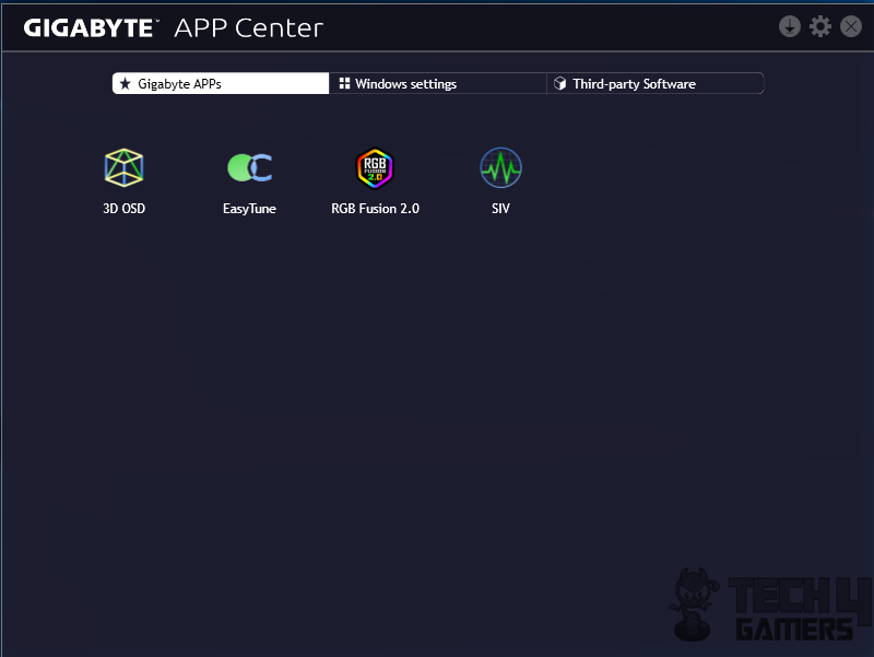
The main interface of the Gigabyte App Center is plain simple. It has three sections outlined under three tabs. The first tab will show the installed Gigabyte applications.
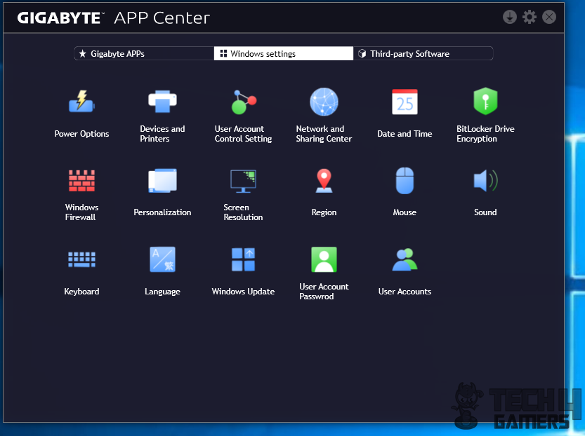
The Windows Settings will show the settings that are available in the Control Panel of the Windows.
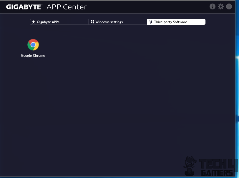
The Third-part software will list the other installed software that are not from Gigabyte or Microsoft Windows.
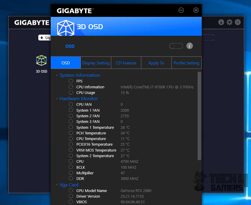
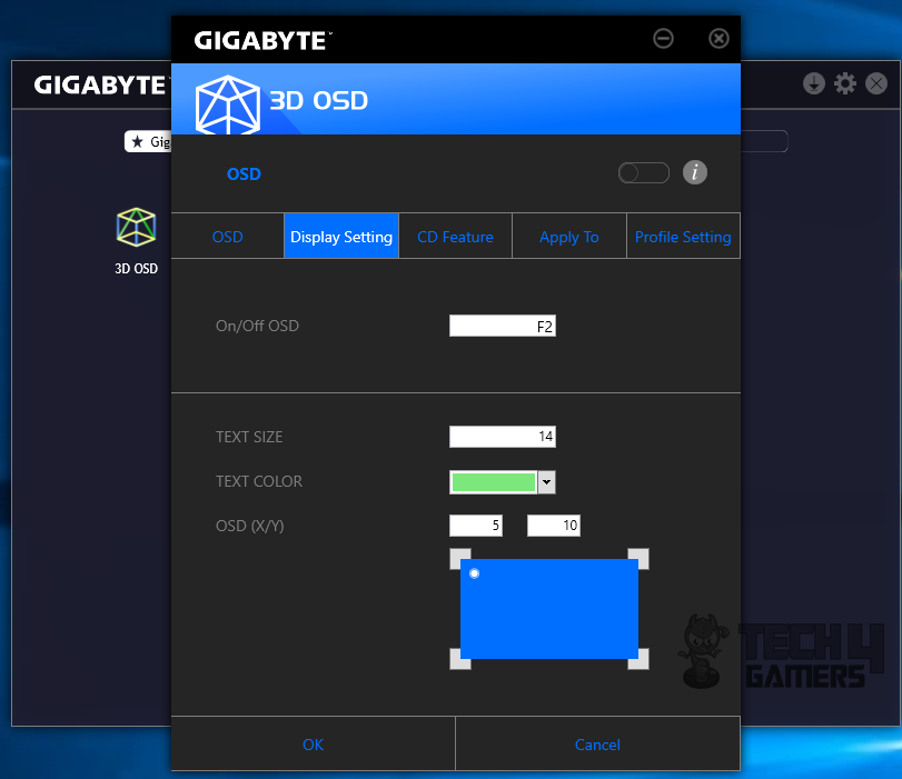
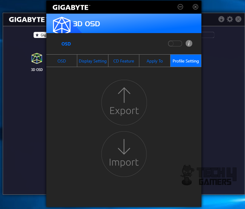
3D OSD is the Gigabyte’s way of monitoring and showing On the Screen Display parameters. We have FPS, CPU Usage under the System Information head. Then we have the Hardware Monitor section that monitors the temperatures of the key areas, the speed of the connected fans, CPU frequency, BCLK frequency, RAM speed etc. Similarly, installed Graphics card’s key parameters can be monitored. The display setting will allow the user to toggle OSD on/off button, text size and color and its position on the screen. The Profile Setting will let the user import/export settings. To enable the OSD, Click on the toggle button above the tabs.
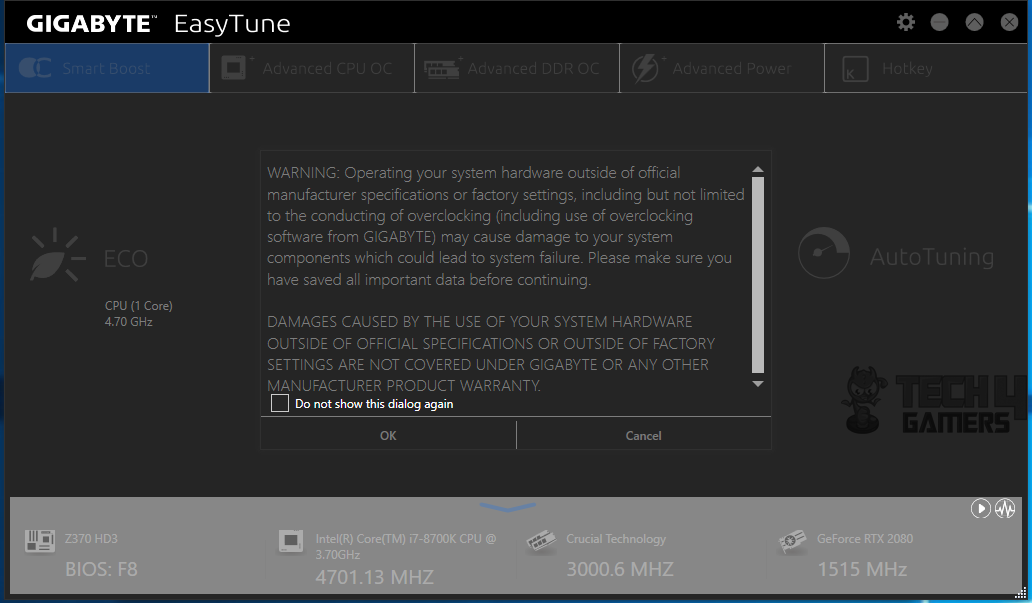
The key application, in my opinion, is EasyTune that lets the user do everything using the software that could be done in the BIOS. Though I am a sort of person who would like to do things manually and from the BIOS, I like the user interface, its simplicity, and effectiveness that EasyTune provides. Job well done, Gigabyte. Launching the app will first show a warning to the user that changing the variables behavior beyond the manufacturer suggested limits could damage the board which will not be covered under the warranty.
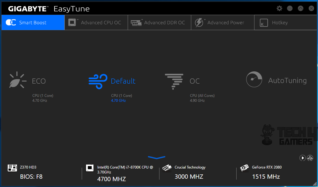
Right, what is the fun in that warning! Click ok (at your own risk) and proceed. The main section is divided into 5 categories. The default is Smart Boost. Other options are Advanced CPU OC, Advanced DDR OC, Advanced Power, Hot Key. The Smart Boost has four profiles:
- ECO Mode is the Energy saving profile in which only one core will boost to 4.7GHz (default boost clock on 8700k).
- Default is the Standard mode.
- OC is the Gigabyte’s fined tuned mode that will overclock all the cores to the 4.9GHz.
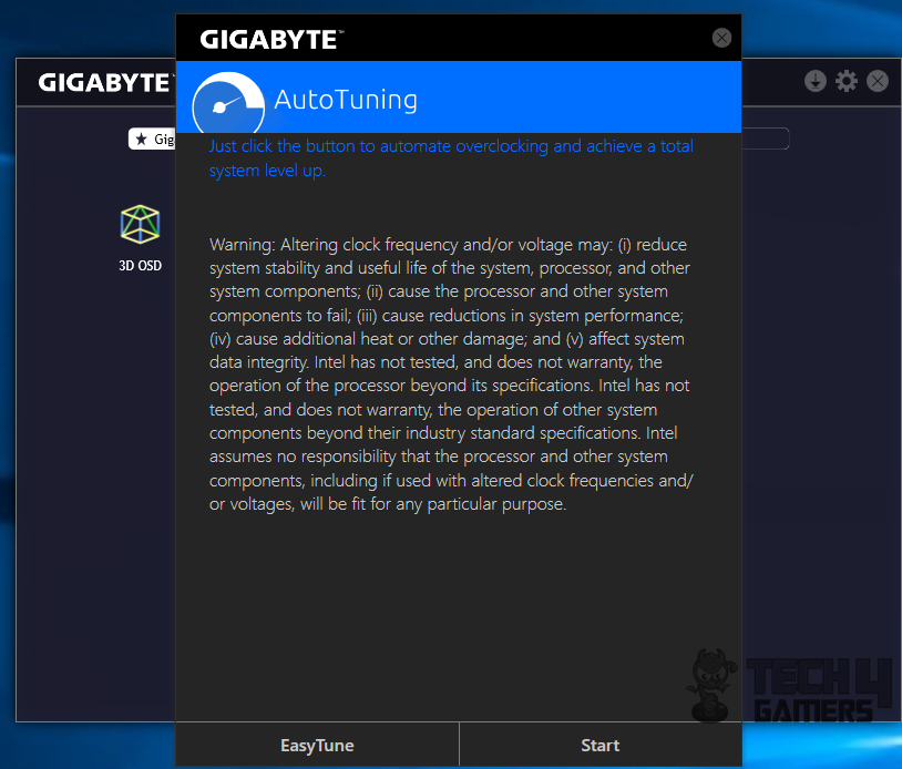
- Auto Tuning will start a wizard to determine the best possible maximum performance settings depending upon the silicon.
The bottom side of this interface displays the Motherboard model along with the BIOS version, CPU model and the speed, DDR manufacture and the frequency, the graphics card model and the speed. Clicking at the down blue arrow will show more options.

Clicking at the small wave button will load the Hardware Monitor window showing the voltages, temperatures, frequencies, and fans speed.
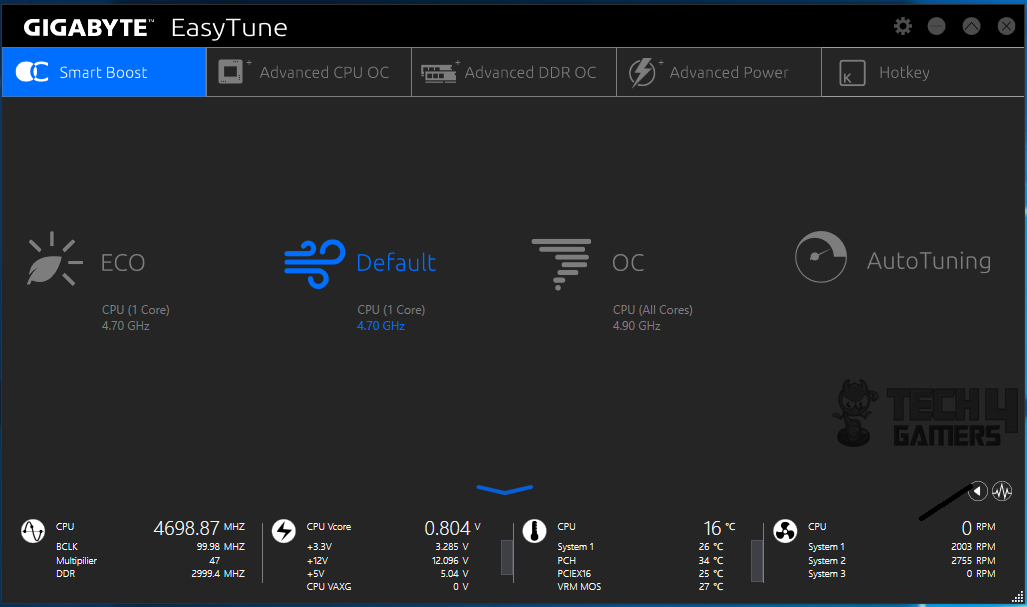
Clicking at the small white color right arrow button will load more parameters and their values on the bottom window like CPU frequency, BCLK, VCore, temperatures, fans speed. This almost reminds me of the AiSuite from Asus.
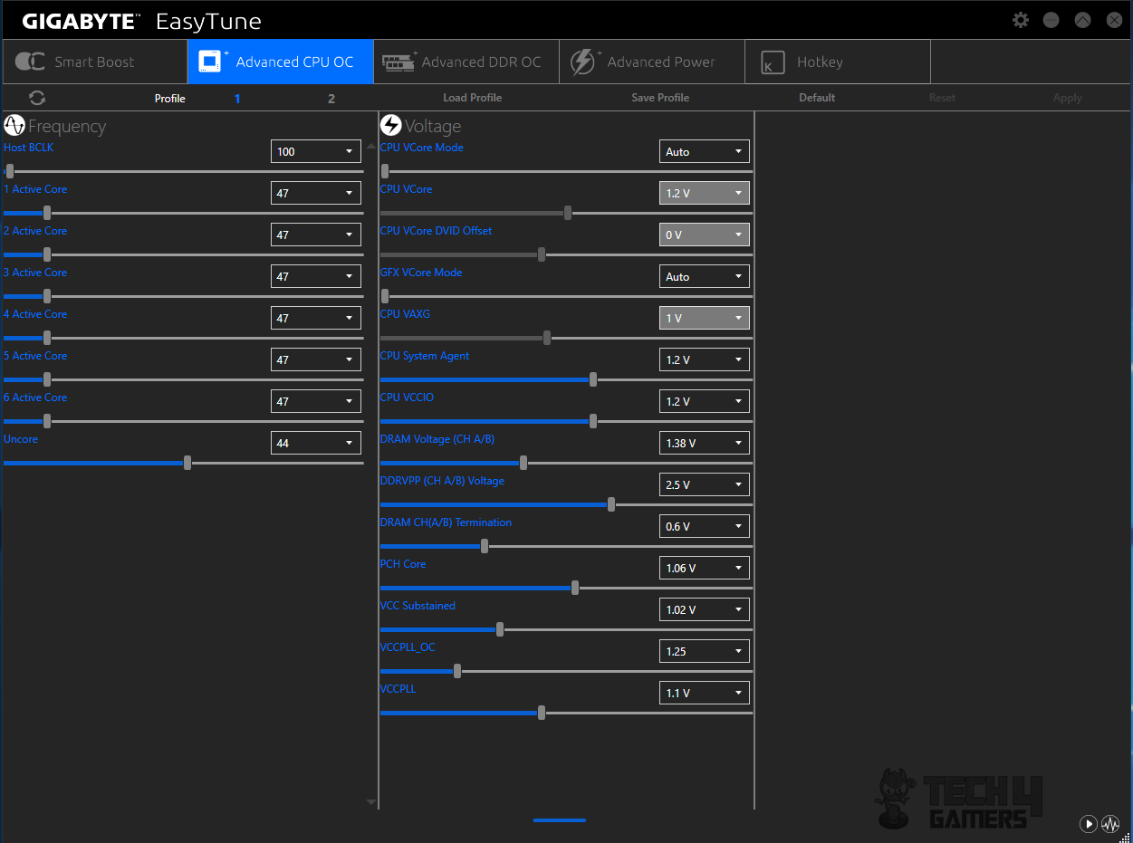
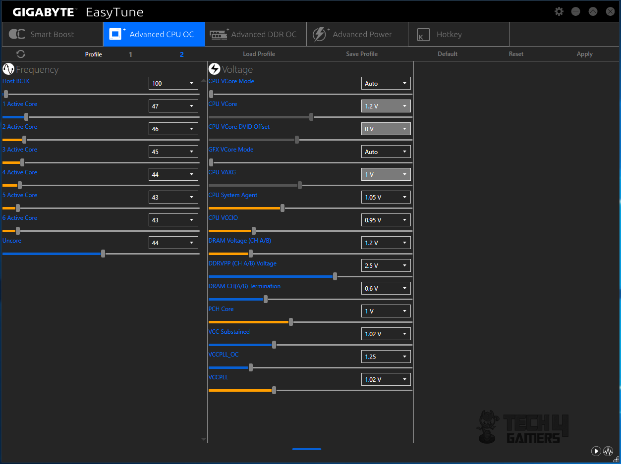
The Advanced CPU OC provides two sections. One covers the individual core and its frequency while the other provides necessary voltages along with the slider to adjust the values. Drop down list shows the available values to be chosen from. There are two profile options at the top. The user can define two profiles which can be saved and loaded from. In case of any issue, the Reset button is there as well. Reset and Apply buttons will be enabled only if the user would make some changes.
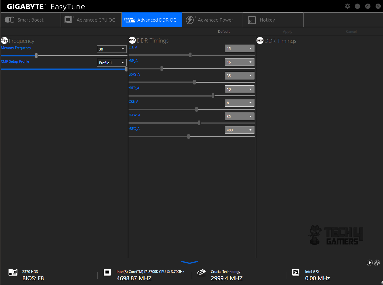
The Advanced DDR OC has a similar interface as is on the Advanced CPU OC except that the left section has DDR Frequency and XMP options whereas the right section allows the users to change the timings of the DDR. No profiling is available on this menu. The default will load the default values of the installed DDR.
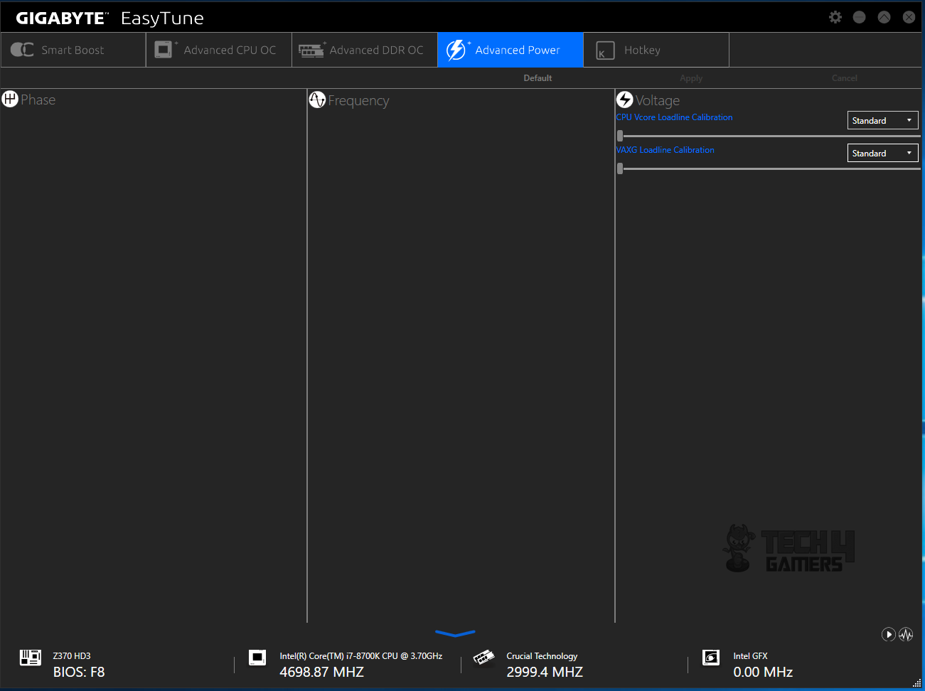
CPU VCore loadline calibration and VAXG loadline calibration are available under the Advanced Power menu.
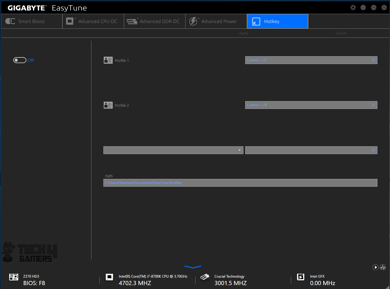
Under the Hot Key menu, the user can define a short cut to save two profiles as well as setting their storage paths.
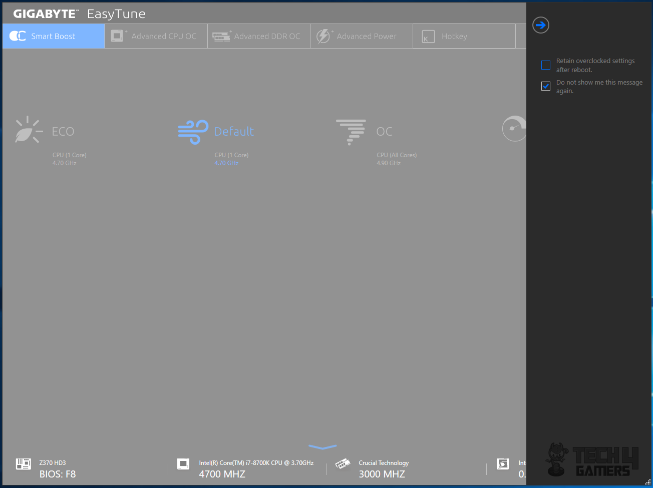
The settings of the EasyTune have two options that will allow the user to retain the overclocked settings after reboot. Defining the settings in the software will override the BIOS settings. Please, be careful when changing the settings.
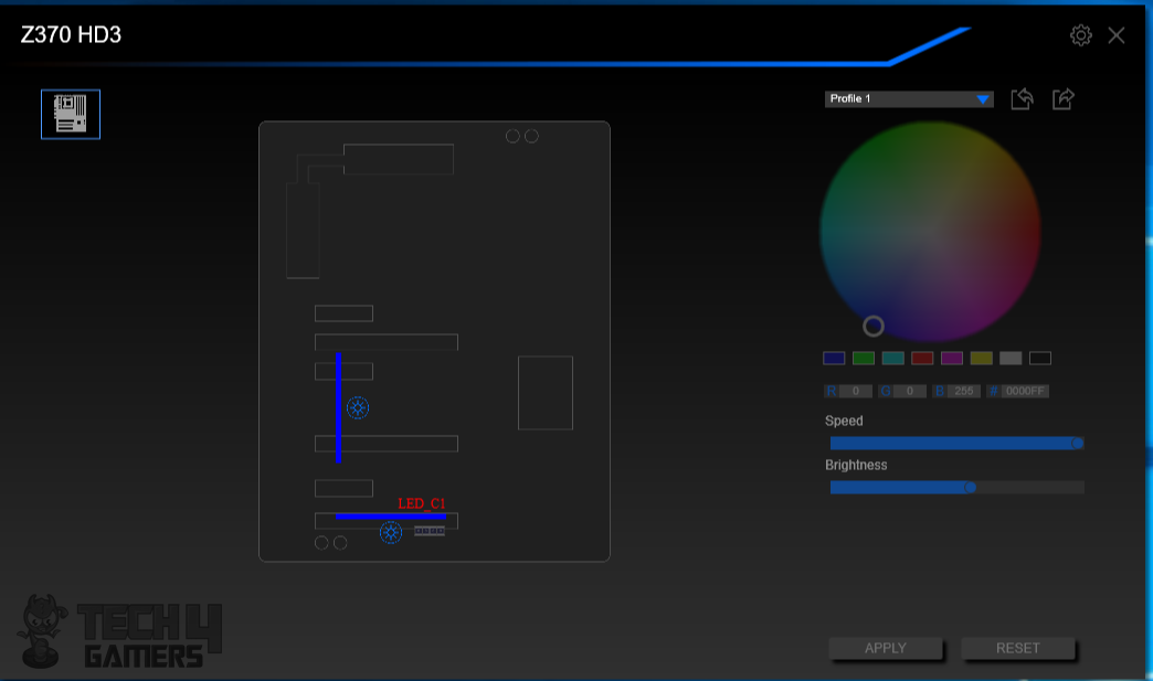
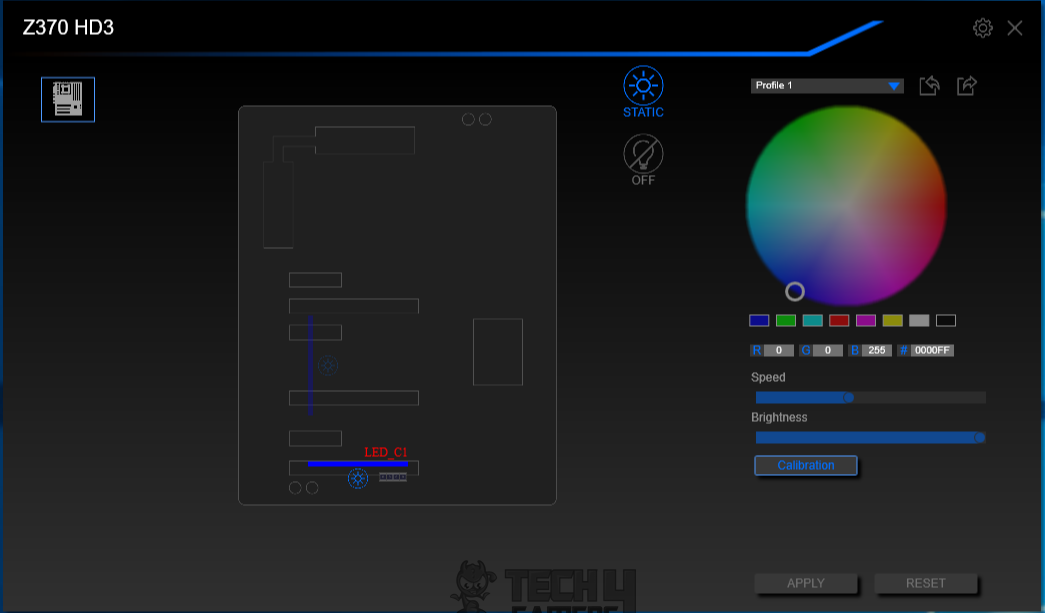
The next app is the RGB Fusion which allows the users to control the RGB Lighting effects on the Gigabyte motherboards and connected (supported) lighting devices. It has a simple interface. The motherboard layout will be displayed on the left side highlighting the possible lighting sources. In our case only 4-pin +12VGRB RGB lighting header can be manipulated using this software as the lining on the Audio PCB is a static and single color. The user can turn off the lighting all together as well. The color combination can be created from the color palette or can be defined using R G B values or HTML code. The speed and brightness can also be controlled.
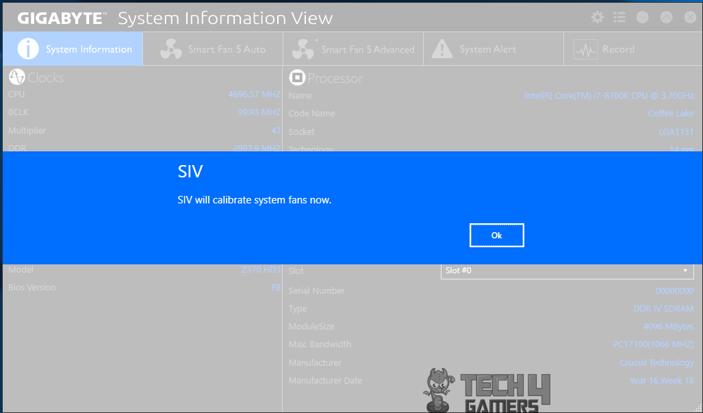
The last app which is another of my personal interest is the SIV. SIV stands for System Information View that will allow to user to control the connected fans’ speed and their sourcing to the thermal sensors as well as defining alarms. Upon launching, the SIV will calibrate the system fans.
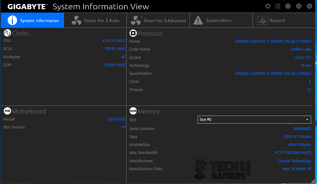
The main interface is divided into 5 menus. The first menu will show the system information including clocks of the CPU, BCLK, DDR, Multipliers, motherboard model and BIOS version, more detailed CPU and DDR information like Socket, Technology, Cores, Threads, DDR Type, bandwidth, manufacturer, and manufacturing date.
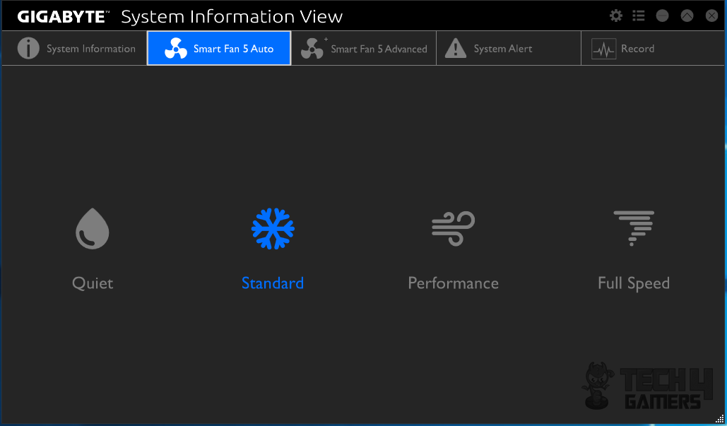
The Smart Fan 5 Auto will show 4 pre-defined profiles for the fans speed:
- Quiet
- Standard
- Performance
- Full Speed
All that the user is needed to do is to click on the desired profile. That is it.
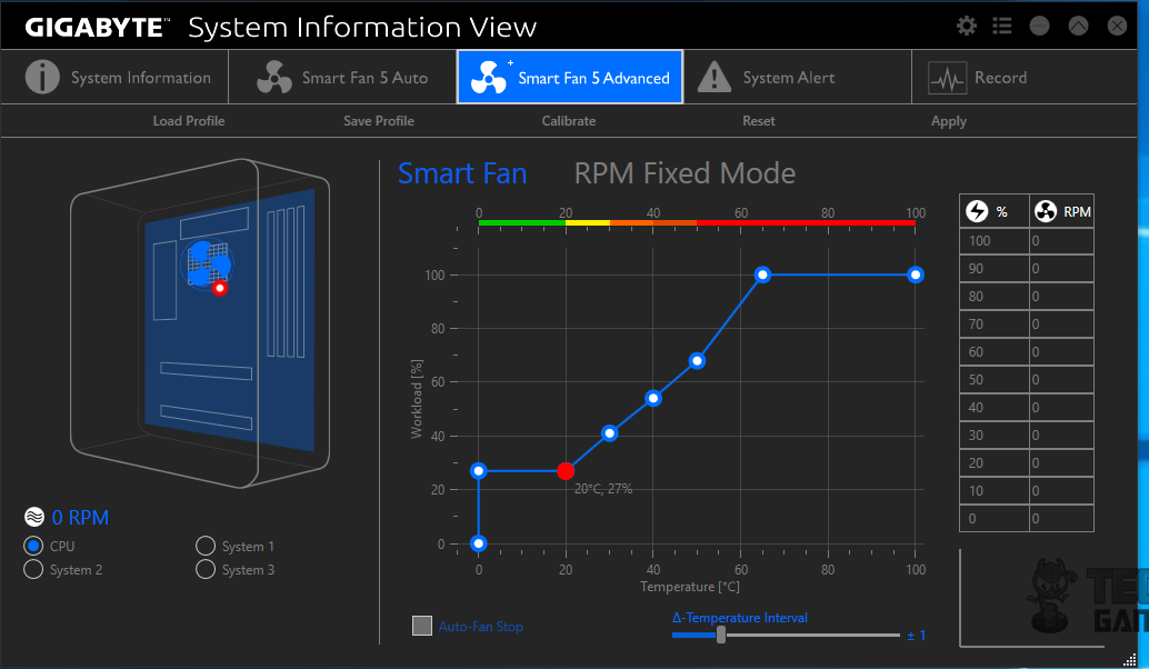
The Smart Fan 5 Advanced has my praise. It is a graphical presentation of what the user can do and with how much ease. On the left side, the chassis diagram is shown with the default selected fan being the CPU Fan. The user can click on the System 1, System 2 or System 3 to select the corresponding fans connected physically on to those motherboard headers. 0 RPM for CPU fan! Surprised? Well, I don’t use CPU fan header or the CPU Opt header for that matter as I want full control over my fans. The way CPU fan header is coded, it will ultimately be controlled by the motherboard. On the right side, the user can define the custom fan curve depending upon the requirement and also set the Auto-Fan stop as well. The user can save and load from the saved profiles as well as calibrate the currently selected fan.
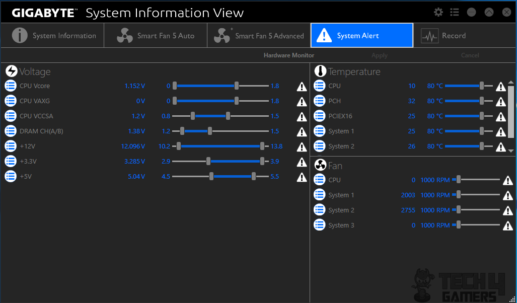
System Alert menu will let the user define the alerts under three broader categories:
- Alerts based on temperature maximum limit
- Alerts based on Voltage threshold
- Alerts based on the Fan’s lower speed.
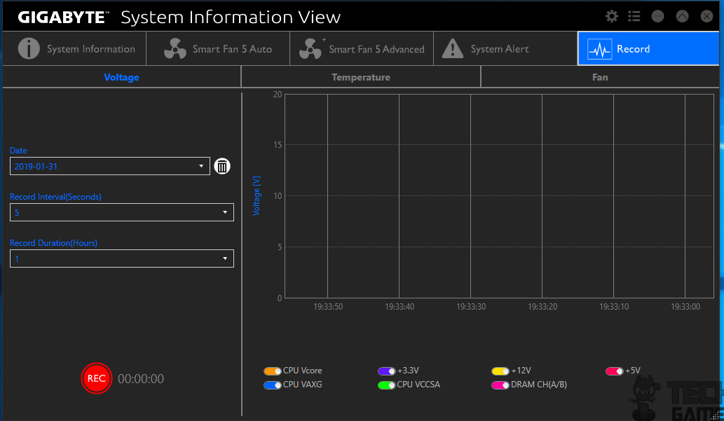

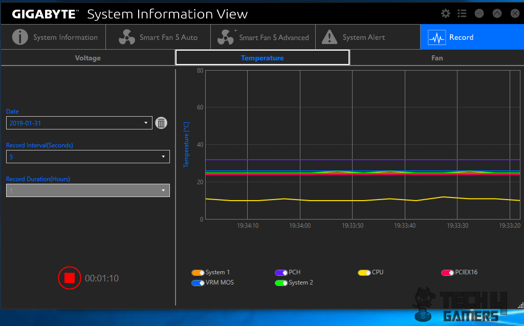
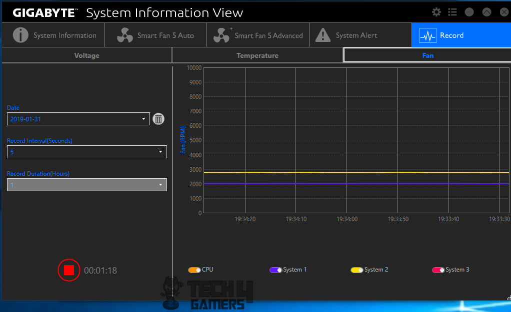
The Record is another interesting and user friendly option that records the Voltages (CPU VCore, CPU VAXG, CPU VCCSA, DRAM CH(A & B), PSU +3.3V output, PSU +5V output, PSU +12V output), Temperature of zones including System 1, PCH, CPU, PCIeX16, VRM MOS, System 2; and connected fans speed. The recording will plot the reading over the given period of time, giving the user a useful graphical presentation of what has been going on with the system.
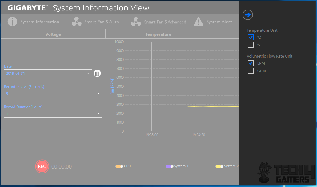
The SIV’s settings allow the user to change the temperature measuring unit from °C to °F and vice versa and change the volumetric flow rate unit from Liter per minute to Gallons per minute and vice versa.
Test Setup
Following test bench setup is used to test the performance of the motherboard:
- Intel i7 8700k
- Gigabyte Ultra Durable Z370 HD3
- Ballistix Elite 4x4GB @ 3000MHz
- Asus GeForce RTX 2080 O8G
- Asus Ryujin 360 CPU Cooler
- Thermaltake Tough Power RGB 750W 80+ Gold PSU
- Adata SX950U OS SSD
- Seagate Barracuda 2TB
Microsoft Windows 10 x64 Pro (1803 update) was used for all the testing. Nvidia 417.35 drivers were used for graphics card testing. Following software were used for performance evaluation: –
Storage Drive Tests:
- AS SSD
- ATTO
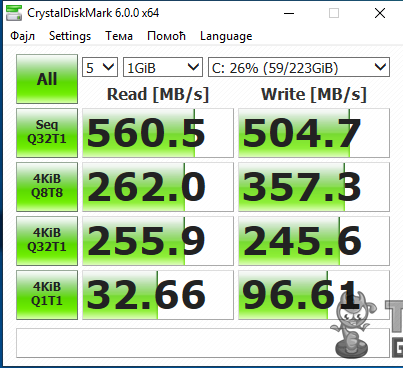
- Crystal Disk Mark
CPU Tests:
- Cinebench R15
- GeekBench 4.0.3
- 7-Zip
- Fritz Chess
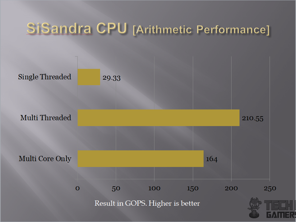
- SiSandra CPU
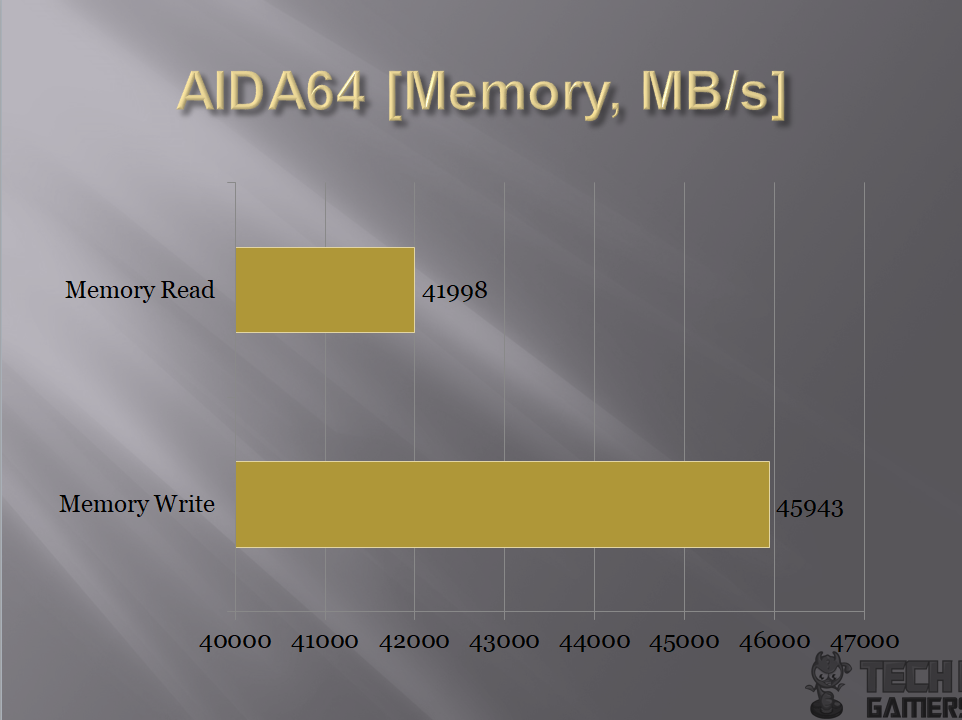
- AIDA64
- Super Pi
Memory Tests:
- AIDA64 Extreme
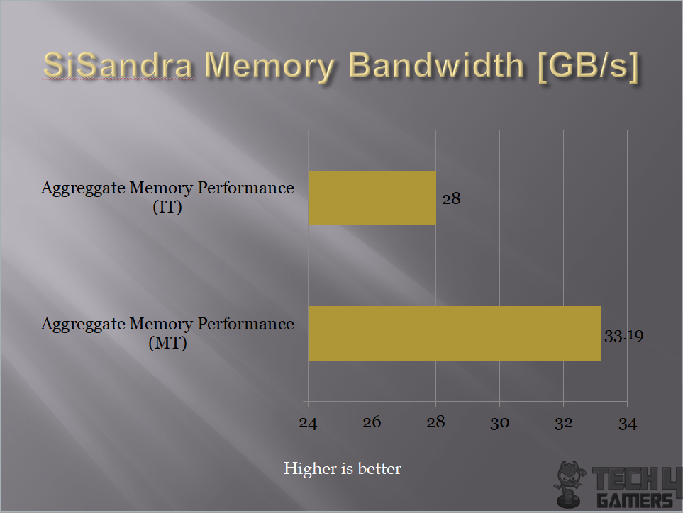
- SiSandra Memory
Overall System Tests:
- PCMark10
- Performance Test
For gaming and synthetic bench of the graphics card following software were used:-
- 3DMark
- Assassin’s Creed Origin
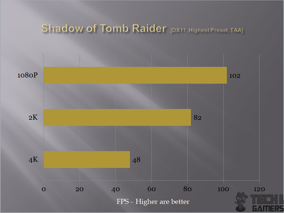
- Shadow of Tomb Raider
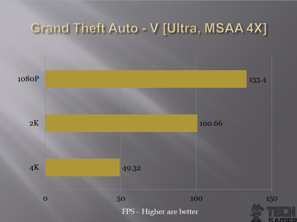
- Grand theft Auto V
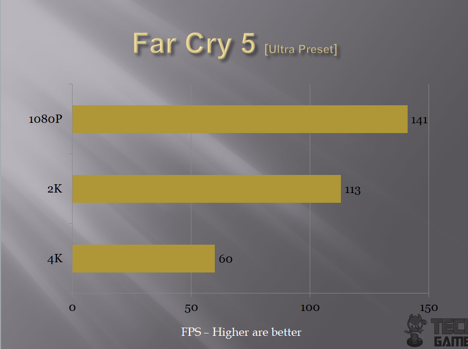
- Far Cry 5
Testing
This section will show the results of the various test suites and gaming benchmarks that we have run on this motherboard.
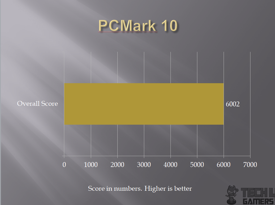
PCMark10 is a comprehensive application suite taking over version 8 to measure the overall performance of the system and the storage devices. Our test build performs relatively well.
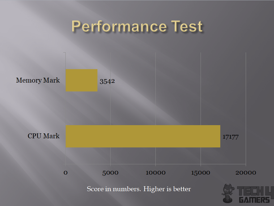
Performance Test or pTest is another comprehensive suite which measures the overall performance of the PC along with detailed tests for each component. I used it to measure the performance of the CPU and the Memory. Scores fall in 95-99% percentile which is a good indication of the performance.
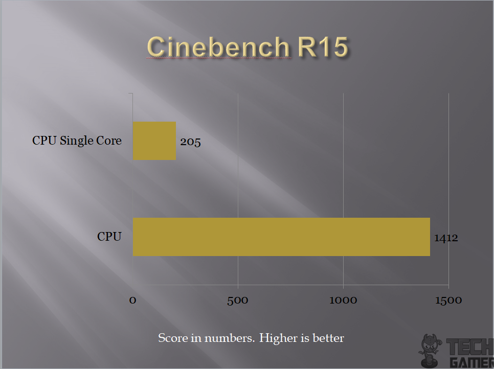
Cinebench is a real-world cross platform test suite that evaluates your computer’s performance capabilities. CINEBENCH is based on MAXON’s award-winning animation software Cinema 4D, which is used extensively by studios and production houses worldwide for 3D content creation. MAXON software has been used in blockbuster movies such as Iron Man 3, Oblivion, Life of Pi or Prometheus and much more. CINEBENCH is the perfect tool to compare CPU and graphics performance across various systems and platforms (Windows and OS X).
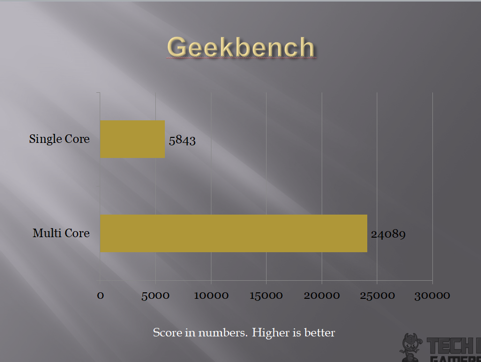
Geekbench 4 measures system’s performance across multiple platforms. The test build performs well under this test. We have used it to test the single core and multi-core performance of the CPU.
Fritz Chess Benchmark is a CPU Performance test. It puts the CPU at 100% utilization and scales among the cores and the threads. The score is recorded as Kilo Nodes per Second and Relative speed.

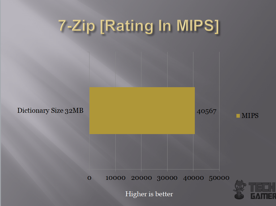
7-Zip is a compression benchmark which utilizes the Memory bandwidth and CPU Cores to measure the performance which is relative. Our graph is showing the overall MIPS.
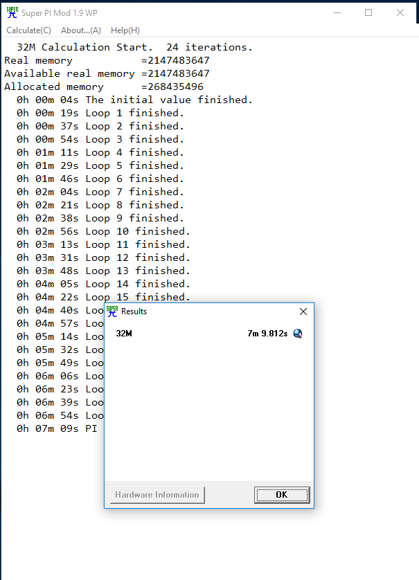
Super PI is a single threaded benchmark ideal for testing pure, single threaded x86 floating point performance and while most of the computing market has shifted towards multithreaded applications and more modern instruction sets, Super PI still remains quite indicative of CPU capability in specific applications such as computer gaming. The lesser the time is preferable.
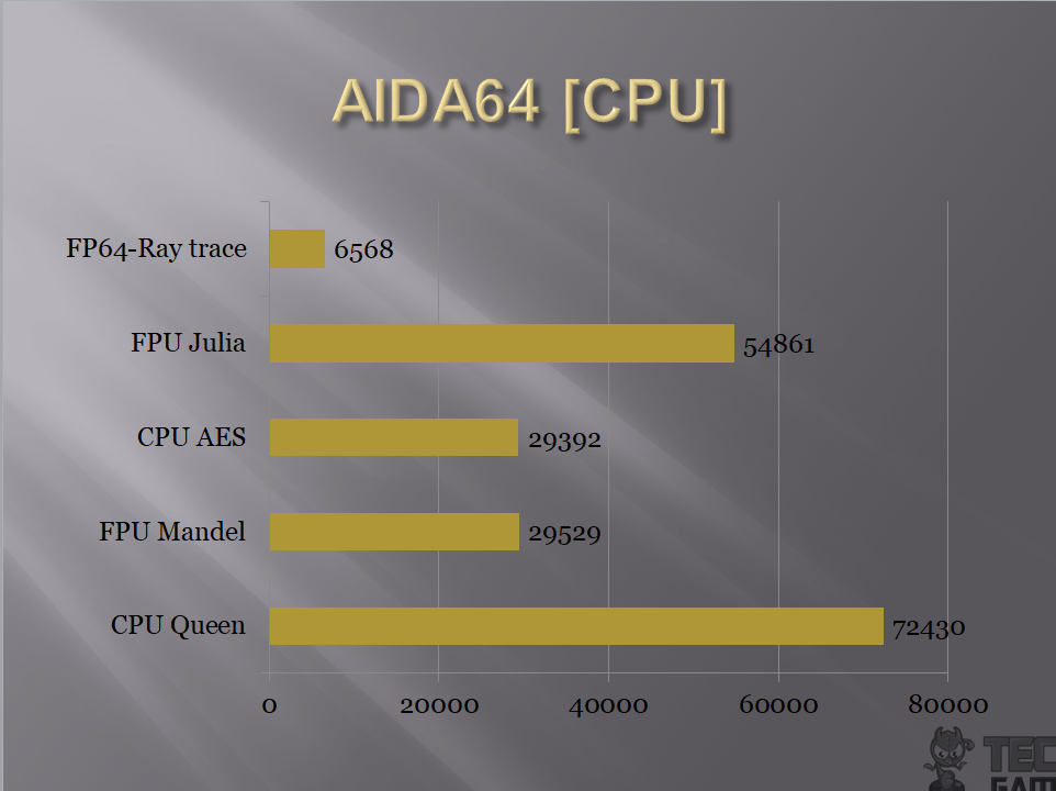
AIDA64 is another extensive application suite to measure the performance and testing the system’s stability. We used it to run some CPU benchmarks and Memory testing.
SiSandra is another comprehensive application suite to measure the performance of the various components of the PC and to check for any reported issues with them. It uses a graphical representation as well as the performance measure. We used it for CPU Performance and Memory bandwidth testing.
CrystalDiskMark is a popular tool to measure the sequential and Random Read and Write speeds of the storage drive(s).
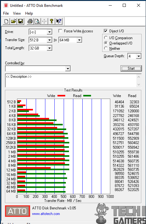
ATTO has created a widely-accepted Disk Benchmark freeware software to help measure storage system performance. As one of the top tools utilized in the industry, Disk Benchmark identifies performance in hard drives, solid state drives, RAID arrays as well as the host connection to attached storage.
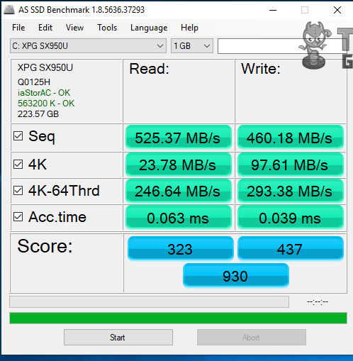
AS SSD software tests the sequential or random read/write performance of the storage drive(s) without using the cache. AS SSD Benchmark reads/writes a 1 GByte file as well as randomly chosen 4K blocks. Additionally, it performs the tests using 1 or 64 threads and it determines the SSD’s access time.
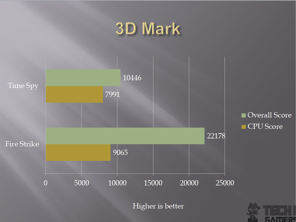
3DMark includes everything you need to benchmark your PC and mobile devices in one app. Whether you’re gaming on a smartphone, tablet, notebook, or a desktop gaming PC, 3DMark includes a benchmark designed specifically for your hardware. We are specifically showing the CPU score only in the graphs.
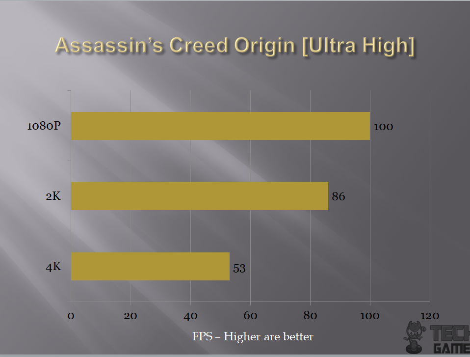
We have tested 4 games on the test build. All the games were tested with their highest graphics settings.

Overclocking, Power Consumption, and Thermals
For the purpose of to the point testing, we disabled the Gigabyte Core enhancement to stay with the Intel defaults. On stock, all the settings were left at Auto. AIDA64 Extreme was used to stress the CPU (CPU, FPU, Cache, System Memory). HWInfo 64 was used to record the power consumption. On stock clocks, the chip was boosting to 4.4GHz using 1.000V VCore. The power consumption of the chip was 53.509W with the system drawing power of 134.127W under load. The maximum temperature while gaming was 42°C whereas it was 50°C while encoding using the Handbrake.
The chip used 1.325V for the 5.0GHz clocks and average temperature under stress at 5.0GHz was 62.5°C. The power consumption of the chip at 5.0GHz under load was 111.006W and that of the system was 219.185W. Please, note that during the testing only CPU was put under load. The graphics card was idling all the time. CPU’s power consumption is as reported by the HWInfo 64 under the CPU Package Power parameter.
Conclusion
The Gigabyte Ultra Durable Z370 HD3 is a budget-friendly motherboard that will allow the users to taste the perks of the Z370 chipset. The PCB is using a gray and black colors combination. The stenciling is nicely done in the gray and black colors which add a subtle touch to it. There is no I/O shroud which is understandable as this is budget friend motherboard so one can spot the obvious areas from where the cost saving is coming besides the hidden ones. We have 4 DIMM slots for DDR4 memories, 6 PCIe slots, 6 SATA ports, USB 2.0 ports, USB 3.1 Gen 1 ports, onboard sound solution, Intel NIC which is GbE, and nice handy I/O provision through the rear I/O section. This motherboard has a new low profile designed chipset cover in gray and black colors pattern which blends in well with the overall layout of the PCB textured pattern and colors. The PCB has ATX form factor measuring 30.5cmX22.5cm and has support for Microsoft Windows 10 x64.
This motherboard packs Intel LGA-1151 socket with 300 series chipset. With BIOS update, Intel Core series of processors in the 9th generation can also be used which is a nice move. The motherboard seems to be using 4+3 power phases. The VRM MOSFETs are covered with aluminum made black color heat sinks for effective cooling. In terms of the cooling solution, this motherboard has 6 thermal sensors including the VRM MOSFET and 4 hybrid fan headers are on the board including the CPU FAN header. To harness the hardware power, Gigabyte has provided an intuitive interface and utility to control the fans. It is called Smart Fan 5. The user has the option to either do it from the BIOS or from the Windows app. The interface is quite user-friendly and Windows app called SIV (System Information Viewer) brings more options on the table than it seems. These fans can be sourced to any of the 6 thermal sensors and the graphical interface is provided for plotting the custom fan curve. These hybrid fan headers can be used for 4-pin PWM fans, 3-pin DC fans, Pumps, AIOs etc.
In terms of the storage, we have 6 SATA ports and one M.2 port compatible with the SATA and PCIe X2/X4 interface using M key type M.2 SSDs with a maximum supported type of 22110. Surprisingly, this motherboard does not have USB 3.1 gen 2 or Type C ports which again may be of cost reduction steps. This motherboard has 4 USB 3.1 Gen 1 ports on the back panel, 4 USB 3.1 Gen 1 ports through the internal USB headers. We have 2 USB 2.0/1.1 ports on the back panel and 4 USB 2.0/1.1 ports through the internal USB headers.
The onboard sound solution is also cut-down version as it is using Realtek ALC892 Codec supporting high definition audio and 2/4/5.1/7.1 channels. It says to have support for S/PDIF output. The audio section is implemented on a dedicated layered PCB. The audio solution is backed by 4 high-end Nippon Chemi-Con Audio Capacitors. For network connectivity, this motherboard has Intel GbE NIC on the board. This is one area where Gigabyte has brought good value to the users. Intel® GbE LAN features cFosSpeed, a network traffic management application which helps to improve network latency and maintain low ping times to deliver better responsiveness in crowded LAN environments.
In terms of the PCIe slots, we have total 6 PCIe 3.0 slots three of which are rated X1. The first full-length slot is rated X16 and is electrically wired to the CPU socket. The second full-length slot is rated X4 and is wired to the CPU socket as well. The third one is wired to the chipset at X4. This motherboard does not support Nvidia SLI but it does support AMD Quad-GPU Cross-Fire and two-way Cross-Fire. The PCIe 3.0X16 slot is not reinforced but Gigabyte has provided a double lock mechanism for better retention.
We have a total of 4 DIMM slots in the black and gray colors. For two modules configuration, use the gray color DIMM slots. These slots are not reinforced so take care while handling the RAM. The latches on both ends of the DIMM slots are to be opened to install the RAM which is unlike the typical design these days in which one end is fixed and the other is used to secure the installation of the RAM. The motherboard supports up to 64GB of DDR4 memory with dual channel architecture using ECC un-buffered DIMM 1Rx8/2Rx8 memory modules and Non-ECC un-buffered DIMM 1Rx8/2Rx8/1Rx16 memory modules. The maximum supported speed or frequency on this motherboard is 4000 (OC) which is indeed a better offering from the Gigabyte given the budget nature of the motherboard. As expected, Intel XMP is supported.
This motherboard is rated at Rs.20,000/- at the time of the review. It packs some nice features that would allow the novice user to enjoy the Z370 chipset functionality and features. I was able to push my 8700k to 5.0GHz and ran stress tests for a longer period to check for the system stability. I have also played games with an overclocked chip. During that testing, the system was indeed stable though I did not get enough time to check for longevity with the OC. I wish Gigabyte had provided debug LED as for troubleshooting we have four onboard LEDs for visual aid and guidance. If any of these light up continuously, it would indicate some issue with the associated component (CPU, DRAM, VGA, BOOT). The BIOS is easy to use as well as this was my first time with the Gigabyte motherboard. Gigabyte has provided ample utilities that the user could take advantage of like SIV, RGB Fusion, 3D OSD, EasyTune. We have covered these in the content. Based on our testing and experience with this motherboard, it comes recommended by us for those who are looking for a Z370 based solution without stressing the wallet.
We are thankful to the Gigabyte for giving us the opportunity to review their Ultra Durable Z370 HD3 motherboard. Easetec is the media partner of Gigabyte in this market. Check them out for more Gigabyte stuff that they have to offer.